How to Design Transmissions That Are Built to Last
Published on April 30, 2025 · 1 min read
The distribution of the load across the gear face width, so called load capacity calculation, will determine lifetime and durability of the gear. As mentioned, FVA-Workbench includes the largest library of methods and standards including the methods for load capacity calculation.
In addition to the geometry and the material used, the load distribution during mesh, when the tooth flanks are in contact, has a significant influence on the load capacity of a cylindrical gear. In the calculation, the influence of uneven load distribution across the face width is taken into consideration via the face load factor K_Hβ (DIN 3990 and ISO 6336) or K_H (AGMA 2101). However, the formulas included in the standards only provide a very rough estimation.
A detailed deformation analysis of the complete gear system is necessary to be able to quantitatively evaluate the effective influences on the load distribution across the face width.
In the FVA-Workbench, the total gear deformation is calculated based on a method developed for FVA and validated using deformation measurements at the FZG at the TUM . The following elastic deformations and static displacements can be taken into account, among others:
- Gear stiffness
- Flank modifications
- Shaft deflection and torsion
- Rolling bearing deflection and clearance
- Casing deformation
- Manufacturing deviations
The deformation analysis in the FVA-Workbench can be performed in a few seconds, even with complex gear structures. The face load factor is automatically determined for each cylindrical gear stage and can be considered in the selected load carrying capacity calculation.
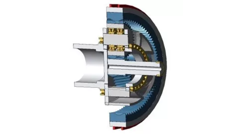
The difference between the ISO approach and the FVA approach for uneven load distribution can be shown on the example of planetary gear stage (Figure 1).
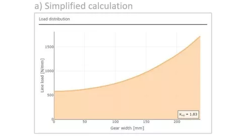
In a simplified calculation according to the ISO standard the load distribution across the face width in this stage is calculated based on the torsion of the sun pinion. The result for this example is a face load factor of K_Hβ = 1.83 with a maximum load on the output side of the sun pinion (Figure 2a).
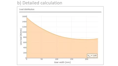
However, if you consider the tilting of the planet gears, the play of the planet bearings, and the elastic deformation of the carrier and pin, the result is a face load factor of K_Hβ = 1.65, and with the maximum load located on the opposite end of the gear (Figure 2b).
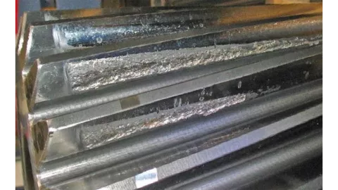
This example demonstrates that a simplified consideration of gear deformations leads to incorrect modification designs in practice, and as a result can lead to one-sided flank damage (Figure 3).
The detailed system-wide deformation calculation in the FVA-Workbench enables a more precise calculation of the load carrying capacity and a practice-oriented optimization of face modifications. This can be used not only to avoid damage, but also to identify hidden load carrying capacity reserves. Cost savings can then be achieved by reducing component sizes and the associated resource usage.
The influence of uneven load distribution across the face width can be evaluated in standard load carrying capacity calculations using the face load factor K_Hβ. However, uneven load distribution across the tooth height cannot be represented in detail.
The following factors can lead to increased flank pressure in the tooth root area of the flank:
- Edge stress in the contact area of the tooth tip edge for helical gears
- Load peaks due to short lines of contact at the start and end of contact for helical gears
- Small radii of curvature at the pinion base with large tooth ratios
- Small radii of curvature near the base circle of a gear mesh
The standard methods assume a suitable profile modification. ISO 6336 (2019) recently introduced the f_ZCa factor to somewhat qualitative consideration of a non-existent or non-optimized profile modification.
With the FVA-Workbench, on the other hand, the influence of uneven load and pressure distribution over the tooth height can be closely examined during gear design. The local load of each point on the flank is calculated for this purpose. Here, too, proven calculation methods from FVA are applied, in which the local gear tooth stiffnesses are calculated on an analytical basis using a plate model. This analytical approach allows a very high resolution with very short calculation time.
The local load distribution determined in this way forms the basis for additional local load parameters:
- Local flank pressure
- Local tooth root stress
- Local sliding speed and lubricant film thickness
- Local contact temperature
- Local safety against micro pitting
Figure 4 shows an example of the pressure distribution of a helical gear with a tooth ratio of 4, a) without and b) with profile modification, calculated with the FVA-Workbench.
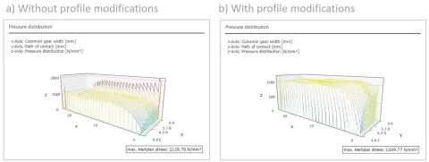
The local pressure increases as the equivalent radius of curvature decreases towards the tooth root of the pinion.
Combining this effect with the edge stresses that simultaneously occurs in the contact area of the tip edge of the mating gear leads to very high local pressure peaks. This requires a profile modification that can be easily designed with the FVA-Workbench. This profile modification ensures uniform pressure distribution across the tooth flank (Figure 4b).
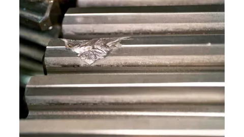
In this way, damage like the triangular flank chipping shown in Figure 5, resulting from these locally overloaded areas are reliably prevented.
Stay tuned
Don't miss the Simulation blog series. Sign up today and stay informed!
Read More About This Topic

NVH calculations provide information about resonant speeds and frequencies, but the cause of resonances themselves cannot be easily determined. In order to find root causes of faults or problems, Root Cause Analysis should be carried out.
The fourth part of this online event series focuses on AVL's simulation solution for electric drive development. Learn about the opportunities that virtualizing can provide. Especially when it comes to using a consistent set of simulation tools for a streamlined workflow.
Powertrain development comes with critical challenges: Will the system hold up under real-world operating conditions? Will it fail under stress or create excessive noise? If these uncertainties are not addressed, the result can be costly development delays and redesigns.
AVL EXCITE™ M provides answers before problems occur.
Stay tuned for the Simulation Blog
Subscribe and don‘t miss new posts.