PEM Electrolyser Development Supported by Multiphysics System Simulation
Published on July 15, 2025 · 17 min read

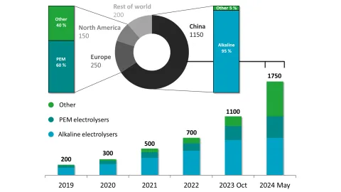
Over the past year, global electrolysis capacity has grown by approximately 60%, reaching 1.75 GW of installed water-splitting power. Alkaline electrolyzers continue to dominate the market, accounting for the majority of this capacity, especially in China. However, PEM electrolyzers are gaining traction, particularly in Europe and North America, where they now represent a significant share.
The main advantages of PEM electrolyzers are fast response, high power density, and low-temperature operation, making them ideal for integration with renewables. Their high current density, precise controllability, and modular design support both scalable industrial use and distributed energy systems. Despite the promising capabilities of PEM systems, the design, testing, and optimization of electrolyzer configurations remain challenging and resource-intensive efforts, particularly when scaling up for industrial applications. Advanced simulation methods have emerged as a promising solution to these challenges, enabling researchers and engineers to model complex electrochemical and thermodynamic interactions accurately.
In this work, we demonstrate how AVL is utilizing system simulation in the development process for design, integration and validation of a PEM electrolyzer system. The simulation framework was rigorously validated against experimental data reported in the literature, ensuring that the model reliably reflects real-world performance and captures the dynamics of mass and heat transport as well as the electrochemical processes. The model was adopted to demonstrate its usability at various stages of the development process, beginning with concept design and component sizing, followed by the development of control functions for different transient operation scenarios. This paper will focus in greater detail on specific use cases: transient dynamics such as warm-up transitions, load-point changes, and hot stand-by operation.
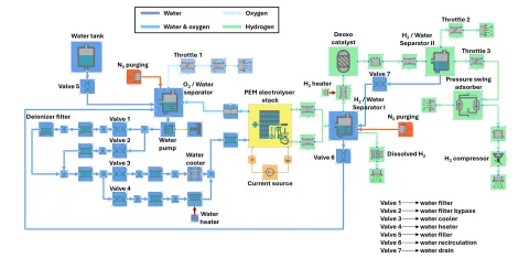
The PEM electrolyzer model generation and simulations were carried out in the modular dynamic system platform AVL CRUISETM M. The overall system is very similar to the one reported by Stansberry and Brouwer [2], however additional modifications are included in this model. The system is designed to produce hydrogen for injection into a natural gas pipeline at a pressure of 70 bar, with a maximum production rate of 1 kg/h and target purity of 99.999 %. The PEM electrolyzer stack consists of 66 cells with an active area of 200 cm2.
Figure 2 displays the PEM electrolyzer system model, with the major flow paths and components explained in further detail in the following. On the anode side, water from a tank enters the O₂/water separator, with flow regulated by Valve 5 to maintain a 0.5 liquid fraction. A pump directs water through a deionization filter or bypass via Valves 1 and 2, guided by conductivity sensors. During warm-up, all flow passes through a Heater to reach target temperature, after which electrolysis begins. Heating is then controlled via Valves 3 and 4 and pump speed to maintain thermal balance. Oxygen is collected in the separator and released at 1.1 bar, with Throttle 1 adjusting pressure for high-pressure operation.
On the cathode side, hydrogen is separated from water in H₂/water separator I, preheated to avoid condensation, and passed through a Deoxo catalyst to remove residual oxygen. A condenser removes water vapor, with condensed water recirculated via Valve 7. Hydrogen reaches ~99.9% purity, or up to 99.999% with additional PSA purification, and is compressed to 70 bar. At start-up, nitrogen purge ensures an inert environment before electrolysis.
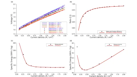
The system model was validated against the data reported by Stansberry and Brouwer and the simulation results were compared to the reference data. In all cases, a strong agreement between the simulated and referenced results was observed, with only minor deviations arising from uncertainties in cell and stack geometries, the ageing status of the components, and variations in operating conditions (Figure 3). Additional factors, such as potential measurement inaccuracies and fluctuations in catalyst activity, may have contributed as well
The model was used to demonstrate its applicability at various stages of the development process, beginning with concept design and component sizing, followed by the development of control functions for different transient operation scenarios. In the following, selected use cases are described in detail: transient start-up, load-change, and hot stand-by operation.
Transient Start-up Process
Developing and calibrating control functions within a virtual environment is a crucial step in accelerating early-stage design, reducing the need for expensive test operations, and safeguarding the physical system from potential damage. While the control strategies for steady-state operations are relatively simple, the implementation of transient control, particularly for processes such as warm-up, remains challenging due to the extended timescales involved. Simulation enables comprehensive virtual testing and refinement of these control algorithms, facilitating a more seamless transition to real-world operation while improving system stability and overall efficiency.
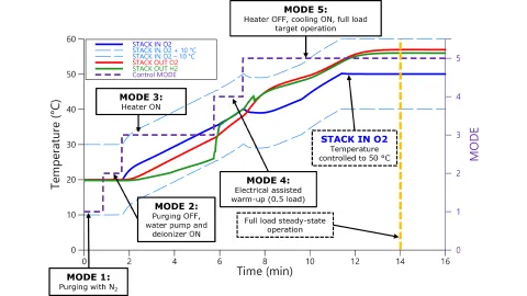
The warm-up process employed in this study is comprised of five stages (Figure 4). In the first stage, both anode and cathode sides of the system are purged with nitrogen gas, which ensures that there is no residual oxygen on the cathode side and hydrogen on the anode side. This is critical to ensure both safety and system performance, as the presence of residual gases can lead to uncontrolled side reactions, efficiency losses, and most critically, the formation of an explosive H2/O2 mixture within the system. The next step involves establishing a water flow system that includes a pump and a deioniser. Deionisation is a necessary step to remove potential ionic contaminants that may originate from sources such as pipes, tanks, or other system components.
In the third step, the heater is activated to gradually increase the water temperature on the anode side, considering temperature gradients to ensure controlled heating. This is followed by the fourth step, in which the electrically assisted warm-up phase begins with part-load operation. As electrolysis begins, the exothermic nature of the reaction leads to a rapid increase in cathode temperature.
Once the system reaches the targeted operating temperature in the fifth and final step, the heater is deactivated, and the current is gradually increased to full load. At this stage, thermal stability is maintained through active cooling, ensuring precise temperature regulation of the water stream temperature. Full-load hydrogen production is reached almost immediately after switching to Mode 5 (approximately 7 minutes), whereas thermodynamic steady-state stability is achieved after 14 minutes, marking the end of the warm-up sequence.
Load Change
Reliable load change operations in PEM electrolyzers are essential for system stability, efficiency, and durability under transient conditions, particularly in the context of renewable energy-driven hydrogen production. As power inputs fluctuate due to the variability of wind and solar energy, understanding the electrolyser’s dynamic response is crucial for maintaining performance and preventing operational instabilities (Figure 5). In this study, the operational load of the PEM electrolyzer was systematically reduced to lower load limit of 25% for a duration of 250 seconds before returning to full-load conditions. Upon load reduction, the rate of electrolysis decreased proportionally, leading to a significant decline in heat generation within the stack. This reduction in thermal output resulted in a decrease in the anode outlet temperature from 55 °C to approximately 51 °C. Notably, the stack inlet temperature on the anode side was consistently maintained at 50 °C through precise valve regulation.
The difference between stack inlet and outlet temperature on the anode is also indirectly controlled by the water flow through the stack. At full-load operation, the water pump operates at rated speed, which maintains the stack temperature difference of 5 °C. Reducing the water pump speed decreases the flow rate through the stack, thereby increasing the residence time of water within the stack. This prolonged exposure allows the water to absorb more heat generated during operation, resulting in a higher outlet temperature. Reducing the load on PEM electrolyser decreases the current passing through the system, leading to a significant reduction in heat generation within the stack.
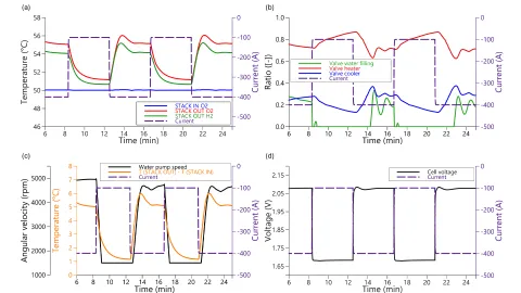
This diminished thermal output reduces the necessity for active cooling, allowing for a more passive thermal management approach. However, maintaining a minimum water flow lever specified by stack supplier results in a stack temperature difference of approximately 1 °C. Concurrently, the decrease in current correlates with an increase in cell voltage, rising from about 1.7 V under 25 % load to nearly 2.1 V at full load conditions.
Hot Stand-by Process
Hot standby operation is one of the crucial operating modes for PEM electrolyzers, especially when trying to optimize LCOH together with variable renewable energy sources. In this mode, the electrolyser maintains its operating temperature and pressure without hydrogen production, enabling rapid resumption of full operation within seconds. This readiness minimizes thermal cycling, which can degrade system components and reduce lifespan. Additionally, it reduces energy consumption compared to complete shutdowns, as it avoids the extensive energy required for reheating, particularly beneficial when system operation resumes after a short downtime.
The virtual hot standby experiment begins by bringing the PEM stack to its full‑load setpoint, with the current held constant to elevate the cell to 50 °C. At t = 10 min, the current is reduced to zero, immediately halting the electrolysis and preventing heating of the feed water. As conductive and convective losses then drive the stack outlet temperature downward, the auxiliary heater is turned on and the cooling valve (Valve 3) is gradually closed. Heater power rapidly rises and converges to approximately 0.7 kW, exactly offsetting the system’s intrinsic heat losses and maintaining the 50 °C setpoint (Figure 6).
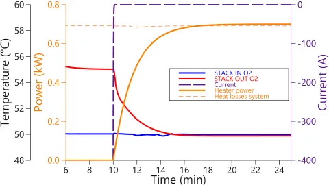
By avoiding full shutdown, the hot‑standby strategy minimizes thermal cycling stresses on the membrane and catalyst layers, preserves component durability, and enables an almost instantaneous return to electrolysis once the current is reapplied.
PEMEL Stack Wizard
The simulation software AVL CRUISE™ M offers a broad range of model features and simulation capabilities, including a PEMEL Wizard designed to streamline stack modelling and parameterization. With its guided workflow, users are supported through a structured and intuitive process to calibrate their stack models using either steady-state or transient measurement data. The user-friendly interface integrates seamlessly into the existing PEMEL stack component, making it easy to access and ensuring a smooth transfer of parameters. The wizard enables parameter optimization across up to 14 selectable inputs, allowing for flexible and precise calibration tailored to the user’s dataset. To support model validation and tuning, the tool also offers advanced output analysis, including parity plots and polarization curves, providing immediate insight into the quality of the fitting and model behaviour. This functionality empowers engineers to develop accurate, high-fidelity PEMEL models more efficiently, and paves the way for faster innovation in hydrogen technologies.
PEMEL System Generator
One of the biggest challenges in engineering is the lack of clear modeling methods, often worsened by incomplete component data.
To tackle this, we developed the PEMEL System Generator that streamlines consistent, scalable hydrogen system modelling and minimizes manual setup (Figure 7).
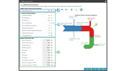
H2 Production Power: The generator starts with a simple input: the target hydrogen production power (based on Higher Heating Value). This serves as the primary parameter for generating the complete system layout, including the appropriate scaling of components.
Advanced Model Settings: Users have the flexibility to influence system performance by setting efficiencies for key components:
Compressor Efficiency: This value is applied to the hydrogen compressor, which compresses hydrogen from the system's operating pressure to the storage pressure. Higher efficiency reduces the compressor's power consumption.
AC/DC Converter efficiency: Since the PEM Electrolyzer (PEMEL) stack requires DC voltage and typical grid connections provide AC, an AC/DC converter is necessary. Its efficiency determines the auxiliary power loss during conversion.
PSA Efficiency: During the hydrogen purification process, drying poses a major challenge. Achieving the required hydrogen purity involves using Pressure Swing Absorbers (PSA) or Temperature Swing Absorbers (TSA), both of which introduce notable power losses.
Stack Operating Point: The system is designed to operate at a nominal full-load point, typically defined by the stack’s characteristics. Users can set the "stack current density" and the corresponding "stack voltage," which allows automatic fine-tuning of electrochemical parameters for accurate stack modelling.
Boundary Conditions: The final four inputs allow for control over boundary conditions in the system. These include:
Inlet temperature of the stack coolant
Condenser temperature in the first stage of hydrogen drying
System operating pressure
Hydrogen storage pressure
KPIs: Fast calculation of key performance indicators provides a clear overview of system efficiency. These KPIs include:
Power balances across components
Hydrogen mass flow rate
Specific energy consumption of the stack and entire system
Sankey Diagram: To visually represent the power balances in the system, a Sankey diagram is used. This provides a clear and intuitive overview of energy distribution and losses throughout the system.
Once the user has entered all required inputs and the key performance indicators (as shown in the Sankey diagram) are deemed acceptable and plausible, the system model can be generated by pressing the Finish button. The resulting layout is fixed as an initial configuration and serves as an optimal starting point for any user. Further architectural modifications remain possible and can be applied based on specific needs or optimization goals.
The generated model consists of three main sections:
The Stack and Balance of Plant (BoP) components represent the physical hardware of the complete system, where thermodynamic and electrochemical calculations are performed. Their configuration closely resembles the system described in the first part of this blog.
Control components play a crucial role in the system by regulating pumps, valves, and compressors to maintain the desired operating conditions. These components ensure that the system functions efficiently and stays within its defined parameters.
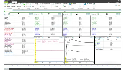
All physical quantities such as pressure, temperature, mass flows, and electrochemical parameters along with other key performance indicators (KPIs), are directed to the Monitor components (Figure 8). This enables real-time observation through a comprehensive Online Monitoring interface, providing all essential system information at a glance. Additionally, the setup includes a Convergence Control component, which indicates whether the system has reached a steady state operating point, ensuring that the simulation results are reliable.
This work demonstrates that advanced dynamic modelling of a PEM electrolyzer not only replicates key experimental performance metrics with high accuracy, but also offers valuable insights into operational flexibility, control strategy design, and long-term durability considerations. Through rigorous validation against literature data, the developed models prove suitable for a wide range of use cases across different stages of the development cycle. The incorporation of aging effects, such as declining stack performance and increased hydrogen crossover, underscores the critical safety and performance trade-offs between operating current density and component longevity important for e.g. LCOH consideration.
By capturing the full spectrum of transient behaviours, the model provides a robust foundation for exploring dynamic phenomena that are often overlooked in steady-state analyses. This includes scenarios such as warm-up phases, load transitions, and hot-standby operation, which were demonstrated as representative transient cases. Identifying optimal operating regimes that balance efficiency, durability, and safety, the presented framework serves as a powerful methodology to accelerate the design, scale-up, and cost-effective deployment of reliable PEM electrolysis systems for integration into renewable-based hydrogen infrastructure.
Literature
[1] M. &. Company, “Hydrogen Insights September 2024,” Hydrogen Council, 2024.
[2] J. M. Stansberry and J. Brouwer, “Experimental dynamic dispatch of a 60 kW proton exchange membrane electrolyzer in power-to-gas application,” Int. J. Hydrogen Energy, 45, 9305-9316, 2020.
Stay tuned
Don't miss the Simulation blog series. Sign up today and stay informed!
Read More About This Topic

Optimize performance and lifetime of PEM fuel cells while minimizing costs
The demand for sustainably generated energy is increasing rapidly, and electrolyzers are seen as a promising technology. Due to their efficiency and good dynamic performance, PEM electrolyzers are one of the most widely used technologies today.

Electrolyzers – the technology at the heart of green hydrogen production – are currently in the focus of intense research and innovation activities, aiming at increased efficiency, minimized performance loss over time, and reducing development effort and time to market.
Stay tuned for the Simulation Blog
Don't miss the Simulation blog series. Sign up today and stay informed!