The driving force in development is to achieve the highest possible performance with the best possible durability and efficiency at the lowest possible cost. Sounds impossible? Especially since there are complex interrelationships behind these goals.
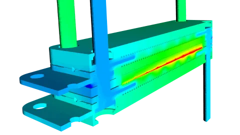
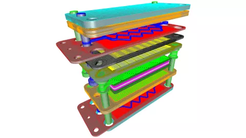
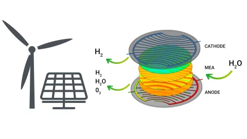
Once the system concept and the requirements for the subsystems and components have been defined, it's time for optimization. To obtain a perfectly functioning system, one must not only deal -with the design of the anode/cathode flow field, but also with the cooling channels and the coolant pressure loss optimization at -cell and stack level. Further consideration must also be given to the membrane electron assembly (MEA) components and the media distribution plate.
At the system level, the balance-of-plant (BoP) components - selection and sizing of compressor, humidifier and ejector technology, the overall design of the cooling system and, of course, the calibration of the control strategy - can then be tuned.
Power Density
Requires optimizing the anode/cathode flow field and the cooling efficiency, starting with the cooling concept and channel design.
Efficiency
In addition to the conceptual design of the fuel cell system, the correct selection of the MEA, the reduction of the pressure drop in the coolant flow and the dimensioning of the BoP components are crucial.
Durability
A well cooled system, optimal media distribution and control strategy are key.
Cost
Physical development work and testing requires prototypes, test environments, time and manpower.
To minimize the risk of conflicts with regard to energy density, efficiency and durability, you can develop a fuel cell system holistically right from the start. Simulation is particularly suited to take these goals into account from the very first concept, well before there is even a prototype.
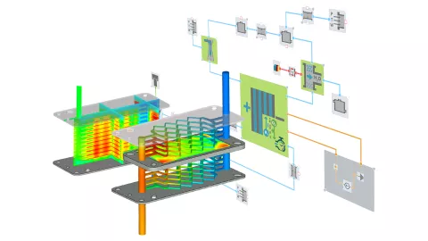
Our single-platform solution enables the ideal interaction of 3D multi-physics CFD and system simulation. (Find out more) You can use the software from the first development steps throughout the entire V-process. Optimize efficiency and performance with consistent PEMFC stack power and degradation models. With the system simulation option, the development and calibration of FCCU functions in SiL and HiL environments is no problem thanks to the full real-time capability.
Scalable Simulation Solution
Accompanies you throughout the entire PEM fuel cell development process.
Consistent PEM Fuel Cell Stack Performance and Degradation Models
3D multi-physics and system simulation provide detailed information regarding the governing degradation processes.
Single-Platform Solution
Facilitates the sharing of data between tools and teams. Additionally supported by the common graphical user interface (GUI).
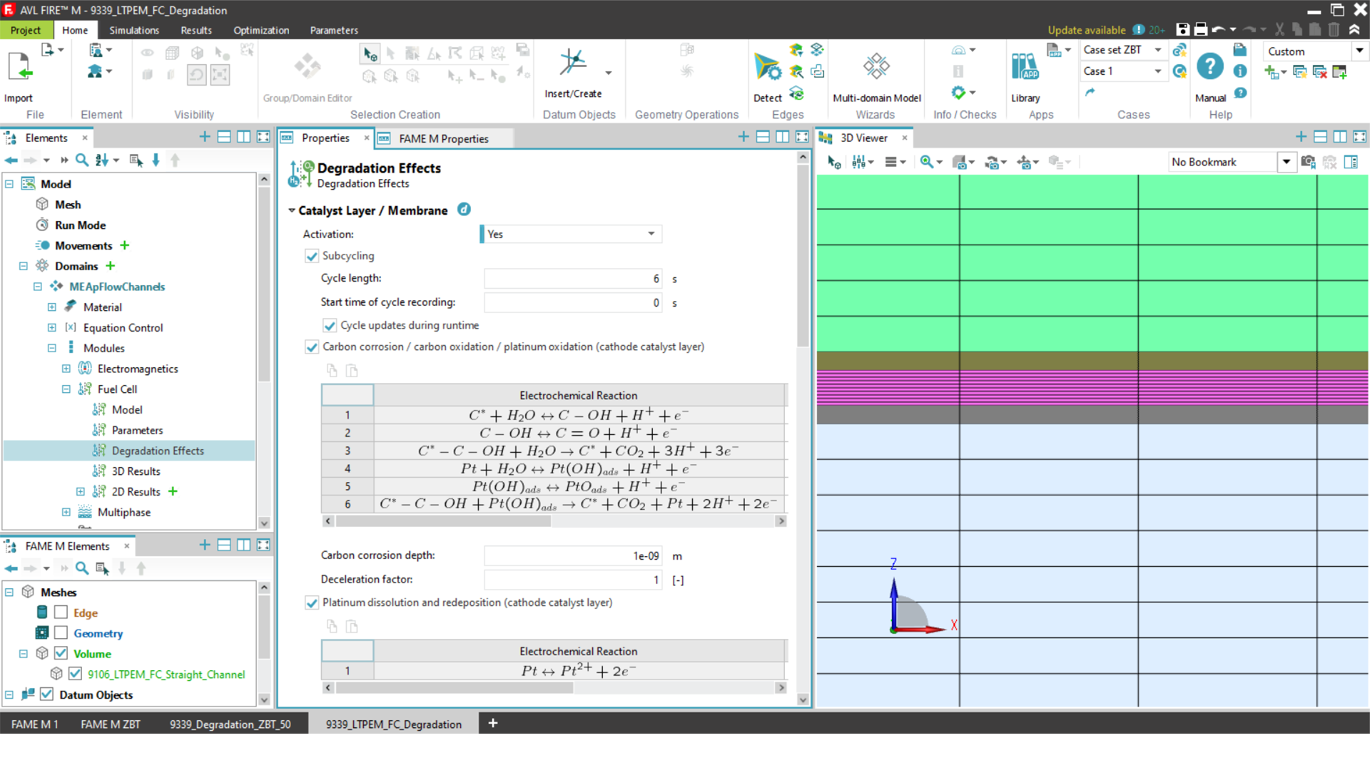
Degradation Models
Our CFD tool AVL FIRE™ M offers you a choice of degradation models:
- Chemical-kinetic models for catalyst layer degradation.
- Chemical-kinetic models for the aging of membranes (ionomer)
- Semi-physical mechanical degradation model
Component Library
AVL CRUISE™ M, our system simulation software, provides you with realistic real-time component models for use in the various system domains.
- Balance-of-plant
- Cooling system
- Electrical, thermal and controls network
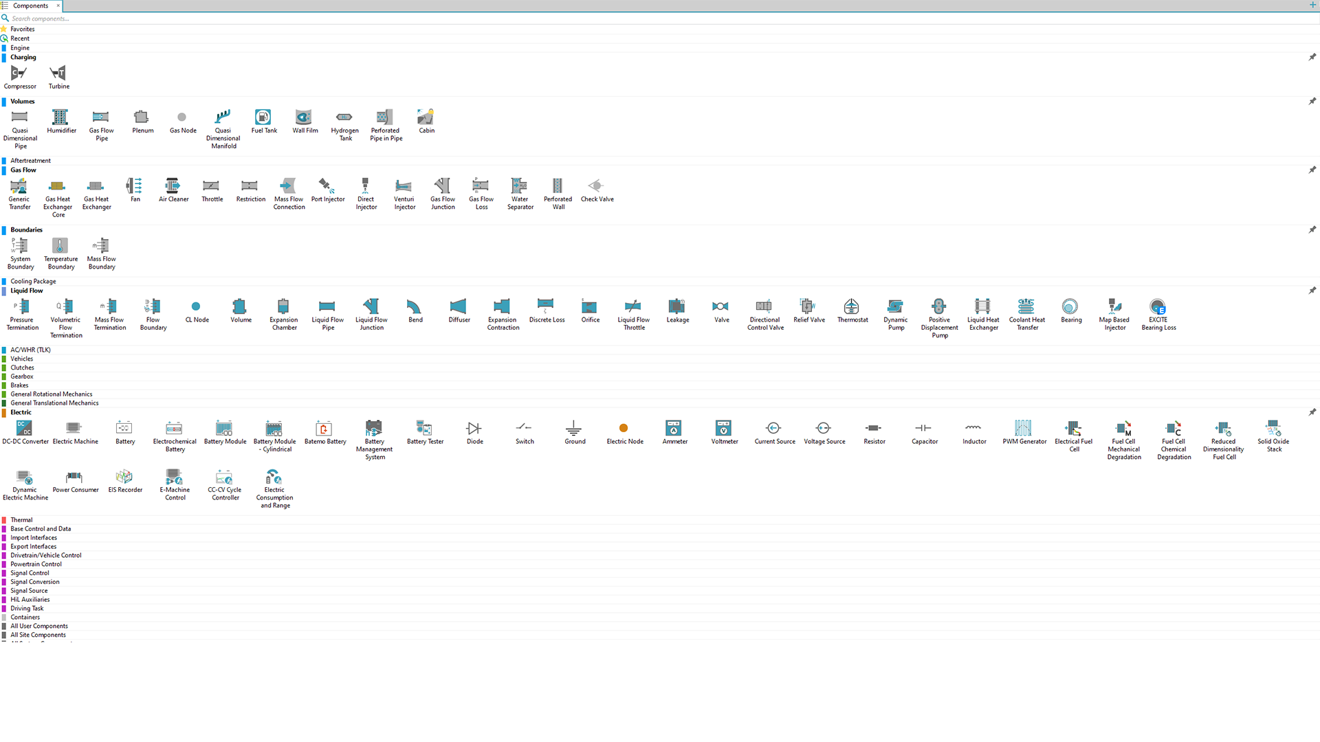
Balance-Of-Plant (Bop) Component Models
To enable you to design a system optimally, CRUISE M has scalable BoP components such as compressor, humidifier, water separator, injector/ejector, H2 tank and many more.
AVL White Paper – Accelerate Fuel Cell Innovation
AVL’s scalable simulation solutions help you design and optimize fuel cells and stacks and their supporting systems, and to make the best integration decisions.
AVL White Paper – Virtual Fuel Cell Performance and Lifetime Optimization - From Component to Vehicle Level
Download our white paper to find out how AVL eSUITE™ helps OEMs and suppliers get the best performance and longest lifespan from this clean power source.
AVL Customer Case Study – Simulation of Fuel Cell Systems at ZBT
In the case of fuel cell electric vehicles (FCEVs) the configuration of the fuel cell system and the traction battery, interaction of the two components in terms of resulting performance, efficiency, and range are particularly crucial.
Due to its scope, AVL FIRE™ M can be described as all-purpose CFD software. However, it is mainly used for the development of all types of powertrains and their components.
The software allows you to view flows around vehicles and objects or heat transfers between any fluid and solid domains in detail.
Data gives one the confidence to clearly decide which concepts to follow. A solid data basis is especially important when mobility concepts are evaluated with regard to multiple factors at the same time. This is exactly what AVL CRUISE™ M stands for.
The demand for sustainably generated energy is increasing rapidly, and electrolyzers are seen as a promising technology. Due to their efficiency and good dynamic performance, PEM electrolyzers are one of the most widely used technologies today.

It is essential to choose the correct cold-start strategy to successfully start a PEM fuel cell system at sub-zero temperatures.In this free, 60-minute webinar, AVL's Dr Reinhard Tatschl and Dr Christoph Pötsch present a multi-physical system simulat

PEM fuel cells offer one of the most promising technology paths towards emission-free mobility.

Performance optimization, increased lifetime and cost reduction are the main drivers behind current PEM fuel cell research and development activities.

The automotive industry is undergoing the biggest transformation in its history. Electrified powertrain technologies are becoming indispensable as the automotive industry seeks to reduce emissions as much as possible.

AVL offers tailored simulation solutions to support engineering tasks during the fuel cell development process to achieve a short time to market.
About AVL
With more than 11,000 employees, AVL is the world’s largest independent company for development, simulation and testing in the automotive industry, and in other sectors. Drawing on its pioneering spirit, the company provides concepts, solutions and methodologies to shape future mobility trends. AVL creates innovative and affordable technologies to effectively reduce CO2 by applying a multi-energy carrier strategy for all applications – from hybrid to battery electric and fuel cell technologies. The company supports customers throughout the entire development process from the ideation phase to serial production. To accelerate the vision of smart and connected mobility AVL has established competencies in the fields of ADAS, autonomous driving and digitalization.
AVL’s passion is innovation. Together with an international network of experts that extends over 26 countries and with 45 Tech- and Engineering Centers worldwide, AVL drives sustainable mobility trends for a greener future. In 2020, the company generated a turnover of 1.7 billion Euros, of which 12% are invested in R&D activities.
For more information: www.avl.com