NVH Root Cause Analysis – A Step-by-Step Guide
Published on February 04, 2025 · 7 min read
The model in our example was designed from scratch with the initial layout for gears and shafts. This was followed by the housing design, including basic topology optimization for stiffness and certain eigenfrequencies. We followed the typical procedure and optimized the microgeometry of the gears to reduce the source of NVH.
The next step is multi-body dynamics simulation to find out what the critical operating conditions are in terms of shaft dynamics, structure-borne noise, and noise radiation. Once we have defined these conditions, they become the targets for subsequent optimization.
How do we identify and understand critical conditions? This is where root cause analysis comes in. Based on the results, we can perform a new optimization of the powertrain housing, trying to reduce the emitted noise. The new design can be verified again with multi-body dynamics simulation and acoustic analysis.
Once your model is complete, you need to transfer it to a multi-body dynamics program such as AVL EXCITE™ M to perform the four steps of root cause analysis to detect potential NVH problems before they occur. One of the tasks is to analyze the deformation shape of the resonance. Cross-influences of resonances and mode shapes can only be done properly in a time-domain solution. EXCITE M performs this analysis in the time domain, allowing engineers to see the interaction of different mode shapes. This is especially important for electric powertrains, where designers must deal with higher frequencies.
The process of root cause analysis consists of asking a series of questions.
First, you must answer the following question: What are the critical speeds at which you want to apply root cause analysis?
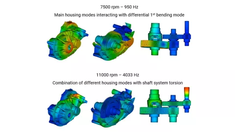
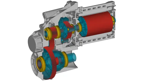
The goal is to reduce noise spikes. To do this, you need to perform an operational deflection shape analysis (ODS). In Figure 1, the example shows two speeds that are the subject of this analysis. The simulations in Figure 1 illustrate the cross-influence between the housing vibration and the differential (bending mode) vibration. In the second case, the shaft system and the torsional system are illustrated.
Move on to the second question for the identified speeds: What excitation path causes the resonance?
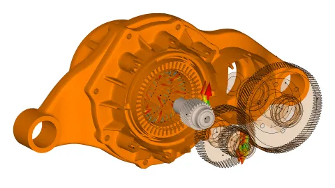
This requires a numerical transfer path analysis (NTPA). In the first step, we saw that there are cross-influences. This vibration is transferred to the surface of the housing, which radiates the noise to the outside. The goal is to find out which bearing the excitation passes through to reach the housing. Take a look at Figure 2 to see the visual output that EXCITE M provides for this analysis. In our example, bearings 4 and 6 transmit the strongest vibrations to the housing.
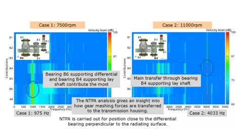
This analysis may seem trivial, but in more complex systems with a larger number of bearings, it becomes life-saving.
Moving on to the third step of the root cause analysis, ask yourself: What operating eigenmode occurs at the resonance frequencies?
We now take a closer look at the NVH performance in different operating modes. For the critical frequencies we have identified, the kinetic energy of the bodies needs to be analyzed. The lower percentage of kinetic energy indicates the higher coupling between eigenmodes of single bodies. The higher percentage is characteristic of the uncoupled eigenmodes of one body.
Finish the root cause analysis with one last question: Which system mode is contributing the most to the resonant vibration?
Answering this question will give you the system mode contribution factor of the assembled system or single body. The important part of this step is to analyze how the bodies behave at the problem frequencies. You should see which body mode contributes to the critical vibration at the given frequency and speed. This information will help you understand how to modify the body to reduce the vibration. In the given example, the obtained results were used for the structural optimization of the housing.
With deeper insight into what is happening when our system is loaded and running we can proceed with the next step – improve our design.
In the optimization process that follows, you have the choice between two methods – either maximize the modes or minimize the equivalent radiated power. The result should be design changes that reduce the vibration at the critical operating conditions.
With the optimized housing of this example, we went back to EXCITE M to closely monitor the effects of these changes. The result in this case is a reduction of the peaks by about 5 db.
Klarin, B., Resch, T., Grozdanovic, I., and Pevec, D., "Root Cause Analysis and Structural Optimization of E-Drive Transmission," SAE Technical Paper 2020-01-1578, 2020: Root Cause Analysis and Structural Optimization of E-Drive Transmission
Stay tuned
Don't miss the Simulation blog series. Sign up today and stay informed!
Learn More About This Topic
The fourth part of this online event series focuses on AVL's simulation solution for electric drive development. Learn about the opportunities that virtualizing can provide. Especially when it comes to using a consistent set of simulation tools for a streamlined workflow.
Through the highest fidelity simulation approach our solution enables the accurate prediction of e-drive NVH. It covers the complete workflow from design to acoustics. The simulation runs in time domain which enables the consideration of physical behavior like it is in reality, without the need to simplify (linearize).
Properly considering the excitation of the e-motor is essential when analyzing the NVH of e-drives. Typically, electromagnetic forces on the stator and torque on the rotor are precalculated using electromagnetic tools.
Stay Tuned for the Simulation Blog
Subscribe and don‘t miss new posts.