E-Motor NVH Simulation: Electromagnetic Excitation Analysis with AVL EXCITE™ M
Published on January 07, 2026 · 2 min read

Electromagnetic excitation in an e-motor significantly impacts its NVH characteristics. The e-motor torque ripple and tooth forces act as excitation sources that influence the motor's dynamic and NVH behavior. These excitations are not constant; they fluctuate due to factors like rotor position and speed, rotor offset, current harmonics and controller settings.
For example, torque ripple, a variation in the torque produced by the e-motor, can lead to vibrations that propagate through the transmission and housing structure. Similarly, tooth forces, which are the forces acting on the stator teeth due to electromagnetic interactions, can excite the motor's housing and other components, leading to structure-borne noise. These excitations can also interact with the motor's structure, amplifying certain vibration modes and potentially causing resonances.
In EXCITE M, these electromagnetic excitations are modeled and analyzed to predict their impact on NVH performance. By simulating these forces, engineers can identify critical frequencies and vibration modes, evaluate the effects of design choices (e.g., rotor eccentricity or stator tooth geometry), and implement measures to mitigate unwanted noise and vibrations. This ensures that the motor operates smoothly and meets NVH performance standards.
A key step in the workflow of high-fidelity e-motor NVH simulation is the extraction of electromagnetic excitation data. The AVL E-Motor Tool™ supports this process by enabling NVH engineers, regardless of their electromagnetic expertise, to generate the necessary input. By providing basic motor geometry, material and a few essential electromagnetic parameters, users can initiate the simulation workflow with minimal manual setup.
Once the input is defined, the tool automatically creates the model and allows users to specify the desired output. A 2D electromagnetic simulation is then performed based on these settings, typically generating excitation data such as stator forces, rotor torque, or other relevant quantities for downstream NVH analysis. The results can be seamlessly exported to EXCITE M for detailed multi-body dynamic simulation, ensuring a smooth integration between electromagnetic and mechanical modeling in the NVH development process.
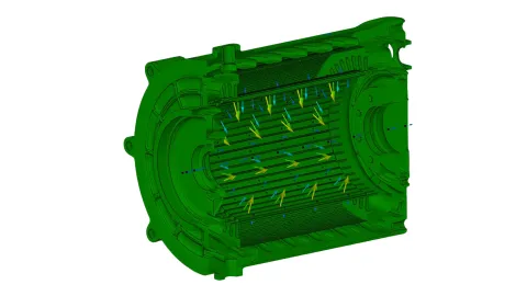
In EXCITE M, the e-motor rotor and the stator are modeled with several slices in axial directions. Each slice is represented by one node on the rotor body and one center or set of circumferential nodes on the stator body. Usually at least one slice represents one e-motor skew section. The e-motor joint applies excitations on these nodes and obtains their motion quantities.
The following electromagnetic excitation workflows are available in the EXCITE M e-motor EMC (Electro-Mechanical Coupling) joint:
- EMC Map-Based Workflow:
Pre-calculates stator forces and rotor torque, offering a straightforward process but neglecting dynamic effects during operation. - EMC Parameter-Based Workflow:
Calculates electromagnetic forces dynamically, considering e-drive movement and torque changes. - EMC File-Based C-C (Center-Center) Workflow:
Dynamically calculates rotor torque within EXCITE M, adapting continuously to operating conditions. E-motor controller is built in the joint. - EMC File-Based C-S (Center-Surface) Workflow (most advanced):
Dynamically calculates rotor torque and stator forces within EXCITE M, adapting continuously to operating conditions. E-motor controller is built in the joint.
Excitation characteristics in EXCITE M refer to the forces or moments applied to a system to simulate dynamic behavior, such as vibrations or noise.
The terms "center-center EMC1" and "center-surface EMC2" describe specific configurations for applying these excitations in e-motor joints:
- Center-Center EMC1: In this configuration, torque is applied to the center nodes of both the rotor and the housing. This setup uses file-based data, meaning the mechanical and electrical systems are coupled, and the electromagnetic simulation provides detailed input data for the joint that also considers the e-motor controller settings.
- Center-Surface EMC2: Here, torque is applied to the center nodes of the rotor, while tooth forces are distributed across the circumferential nodes of the stator. This configuration accounts for eccentricity effects, such as misalignment or rotor tilting, and is also file-based, allowing for detailed dynamic and acoustic analysis also considering the e-motor controller settings. Furthermore, influence of PWM can be considered.
These configurations are used to simulate different physical behaviors and evaluate the impact of design choices on system performance. For example, EMC2 is particularly useful for studying the effects of rotor eccentricity on acoustics and vibrations.
E-motor skewing is a commonly applied design strategy for torque ripple reduction in e-motors. However, traditional analysis methods often rely on multiple 2D electromagnetic simulations, requiring a separate calculation for each skew angle. This can result in significant computational effort, especially when evaluating multiple configurations during design optimization.
With the EMC2 coupling in EXCITE M, this limitation is addressed through a more efficient approach. A single 2D electromagnetic simulation is used to calculate the stator forces for each rotor slice, eliminating the need to run separate simulations for every skew variation.
The skewing is applied to the rotor, which is represented by center nodes in the simulation model. As a result, finite element models do not need to be regenerated when changing skew parameters, enabling streamlined parameter studies and accelerating the overall NVH simulation workflow.
Simulation Results: E-Motor Skewing and Its NVH Impact
Campbell diagrams are commonly used in e-motor NVH analysis to visualize key metrics such as structural vibrations, velocity, and acceleration across operating ranges. While these diagrams provide a comprehensive overview of system behavior, they can be challenging to interpret when evaluating specific excitation sources or harmonic content.
To support more targeted analysis, the simulation workflow includes order cuts that isolate specific frequency components. These order evaluations make it easier to identify dominant excitation orders, assess resonance conditions, and gain clearer insight into the effects of design changes on vibration and acoustic performance.
After evaluating the system response, the next step focuses on the electromagnetic excitation behavior in a skewed rotor configuration. In the example that this article is based on, the rotor is divided into three slices. The first slice is skewed to lead slightly, while the third slice lags behind. The central slice shows minimal difference between the skewed and non-skewed configurations.
However, in the first and third slices, the influence of rotor skewing is clearly visible, both in the timing of the excitation and the amplitude of the resulting electromagnetic forces. These variations impact the overall NVH behavior and highlight how skew angle and segment positioning affect localized force patterns in the rotor structure.
Using NVH Simulation Insights to Minimize E-Motor Torque Ripple
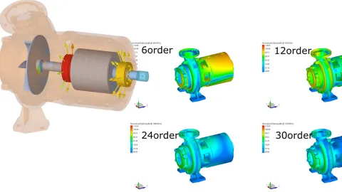
The results in the 48th order (because the e-motor has 48 slots) show a very strong reduction in the torque, based on the stator teeth forces. The simulation results in the 48th order – corresponding to the motor's 48 stator slots – demonstrate a significant torque ripple reduction, directly linked to the influence of stator tooth forces. This order-specific analysis highlights how design measures such as rotor skewing effectively minimize harmonic excitations that contribute to NVH in e-motors.

The Effect of Rotor Offset on NVH
Another parameter with an impact on NVH performance is rotor offset — when the rotor does not rotate exactly in the electromagnetic center of the e-motor. This eccentricity can arise from production and assembly tolerances, bearing clearances, or operational deformations.
Two types of offsets can be distinguished:
- Static offset – typically caused by manufacturing and assembly tolerances, resulting in a constant displacement from the electromagnetic center.
- Dynamic offset – occurs during operation due to dynamic loads, bearing dynamics, or structural deflections, leading to variations in rotor position over time.
In a sliced rotor approach, offset can also introduce a tilt, meaning rotor and stator axis are not parallel. This is particularly relevant for NVH because eccentricity changes the air gap distribution between rotor and stator, increasing certain electromagnetic force harmonics and potentially amplifying vibration levels.
Using the E-Motor Tool, these effects can be modeled efficiently. To parametrize the Center-Surface EMC2 joint in EXCITE M, only two 2D electromagnetic simulations in the E-Motor Tool are needed:
- One with no offset (ideal center position)
- One with the maximum expected offset or tilt
From these simulations results EXCITE M can calculate appropriate stator forces for both aligned and eccentric states, enabling detailed NVH analysis without excessive simulation runs.

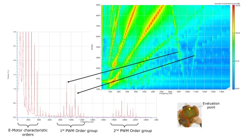
Pulse Width Modulation (PWM) as an NVH Excitation Source
The inverter is a power electronic device that converts the high-voltage DC (direct current) from the battery into AC (alternating current) required to drive the e-motor. It generates an almost sinusoidal alternating current through Pulse Width Modulation (PWM), where the power electronics switch the voltage on and off at high speed to approximate the desired waveform.
This switching process introduces small ripples in the current signal which then results in additional electromagnetic excitations that are typically concentrated at discrete, high frequencies determined by the PWM switching pattern. Depending on the control strategy, these patterns may follow:
- Constant switching frequency – a fixed PWM frequency regardless of speed
- Speed-dependent switching frequency – where PWM frequency scales with motor speed
- Randomized switching – which spreads the harmonic energy over a broader spectrum to reduce tonal noise
In NVH analysis, it is important to consider PWM excitation, as it can interact with structural resonances or other electromagnetic harmonics, especially in higher frequency ranges. With the EMC2 joint in EXCITE M, these effects can be incorporated into the electromagnetic excitation model, allowing engineers to evaluate and mitigate potential noise issues early in the design process.
Electromagnetic excitation is a primary driver of NVH behavior in e-motors — influencing everything from low-order torque ripple to high-frequency tonal noise. In this article, we explored how factors such as rotor skewing, rotor offset, and PWM excitation can significantly alter force patterns and vibration responses, and how advanced simulation workflows make these effects measurable and manageable.
Key insights include:
- Rotor skewing can reduce torque ripple amplitudes at critical orders
- Rotor offset and tilt change the air gap distribution, introducing additional force harmonics that can excite structural resonances.
- PWM switching patterns generate high-frequency excitations that may interact with the mechanical structure.
- EMC2 coupling in EXCITE M enables dynamic, on-line calculation of rotor torque and stator forces, capturing skewing, rotor eccentricity and control-related effects using results from just a few 2D electromagnetic simulations.
- Targeted analysis results such as order cuts and Campbell diagrams provide deeper insight into dominant excitation sources, guiding more effective design optimizations.
By combining the E-Motor Tool for electromagnetic excitation generation with EXCITE M for multibody dynamic simulation, engineers can model both the electrical and mechanical sides of the NVH equation in one integrated workflow. This high-fidelity approach helps detect potential NVH issues earlier, evaluate design trade-offs faster, and optimize e-motor performance before physical prototypes are built.
Watch our full webinar on this topic for practical use cases and expert guidance.
What is electromagnetic excitation in NVH?
Electromagnetic excitation refers to forces generated by electromagnetic interactions in the motor, directly influencing NVH through torque ripple and stator tooth forces.
Why use high-fidelity NVH simulation?
High-fidelity NVH simulation accurately models complex dynamic interactions, enabling early detection and mitigation of noise and vibration issues.
What are the differences between EMC1 and EMC2 configurations in EXCITE M?
EMC1 applies torque to rotor and stator centers, while EMC2 distributes stator tooth forces around the stator circumference, capturing rotor eccentricity effects for detailed NVH analysis.
How does the E-Motor Tool simplify NVH workflows?
It automates 2D electromagnetic simulations and seamlessly integrates results into EXCITE M, allowing NVH engineers to perform advanced electromagnetic analyses without deep electromagnetic expertise.
Stay tuned
Don't miss the Simulation blog series. Sign up today and stay informed!
Read More About This Topic

NVH analysis is typically performed after a problem has been identified that needs to be addressed. In the case of a simulation model used, it is advisable to proactively look for increased vibration and resonance so that the model can be optimized before the first prototype is built.
This article explores NVH analysis of electric water pumps in passenger vehicles, revealing noise and vibration mechanisms and presenting new simulation methods.
At the upcoming AVL SIMpulse we open the black box of bearing behavior inside the e-motor.
The fourth part of this online event series focuses on AVL's simulation solution for electric drive development. Learn about the opportunities that virtualizing can provide. Especially when it comes to using a consistent set of simulation tools for a streamlined workflow.
Stay tuned for the Simulation Blog
Don't miss the Simulation blog series. Sign up today and stay informed!