AVL Simulation Software Release 2025 R1
Published on May 07, 2025 · 36 min read


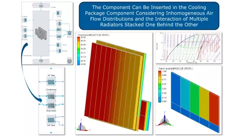
Cooling Package – Gas-Gas and MPET Heat Exchanger Featuring 2D Air Flow
In AVL CRUISE™ M’s Gas-Gas (GG) and multiport extruded tube (MPET) heat exchangers, it was assumed that air, in a cross flow arrangement, enters the radiator in a homogeneously distributed manner. With this version of CRUISE M, the GG and MPET heat exchangers can be inserted into the Cooling Package component, considering inhomogeneous air flow distributions and the interaction of multiple radiators stacked one behind the other.
3D Viewer – Cooling Package, Segmented Pipe and Liquid Flow Network
The introduction of the 3D Viewer, as an add-on to the classical, topology based setup of component networks, is perfect for visualizing the geometrical constellations in cooling packages. When inserting either a Gas Liquid, MPET-2D or Gas-Gas Heat Exchanger into the Cooling Package component, you not only see them in the Topology Editor but also get feedback on their size and position in 3D space.
In addition, you can also inspect your pipe design in 3D. You need nothing more than to activate the 3D Viewer pane and click on one of the Segmented Pipe components. In the 3D Viewer, you can configure camera angles and zoom levels and pick selected elements to move and rotate them.
The 3D Viewer also works for liquid flow networks. When pulling components from the Liquid Flow Library onto the topology canvas, they also show up in the 3D Viewer. When you connect two components in the Topology Editor, their connection is visualized in the 3D representation. When importing a piping system from CAD data, CRUISE M not only creates a corresponding component network but also replicates the known CAD geometry in the 3D Viewer.

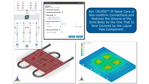
Interactive Connections in 3D – Solid Walls and Battery Modules, Solid Walls and Liquid Pipes
CRUISE M introduces a completely new mechanism to thermally connect 3D Solid Wall, Battery Module and Liquid Pipe components. When placing 3D Solid Wall elements on the topology canvas, you can instantly see how these components are sized and positioned in 3D space. Once you have established this configuration on the topology canvas, you can check the geometrical positioning of the components in the 3D Viewer. There you can move the components, and, uniquely, the Liquid Pipe component can intersect into the bodies of the 3D Solid Wall components.
You do not need to worry about the spatial discretization of the connected components. CRUISE M handles non conform connections and reduces the volume of the solid body by the one that is now covered by the Liquid Pipe component.
When running a simulation, AVL IMPRESS™ M provides a 3D view of the simulated temperature fields and offers all kinds of additional postprocessing functionalities known from CFD.
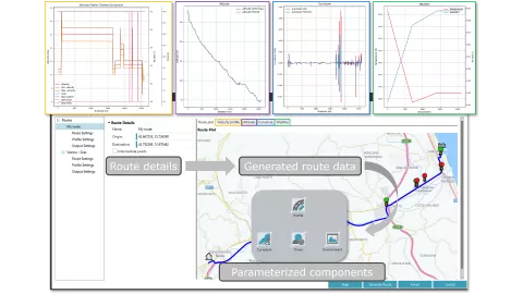
Route Generator – Driving Profiles from Real World Routes
The classical way of assessing vehicle performance is to run standardized velocity profiles (WLTC, FTP75, etc.), as they allow for good comparability between different vehicle configurations. Beyond that, there is the question of the optimal vehicle configuration for a known driving route. With this version of CRUISE M, you can pull route data from HERE, a web based map service, and translate it into a CRUISE M model. To get started, launch the new Route Generator from the Efficiency Portal and follow the guided steps. The routes are specified either by two geographic coordinates or two addresses, from which HERE returns your route on a street map. When closing the Route Generator, the retrieved data is mapped to the underlying Profile, Environment and Curvature components, ready to give your vehicle simulation a more realistic spin.
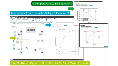
Result Browser – Quick Result Analysis
The analysis of results can be seen as the most important part of a simulation task. This version of CRUISE M addresses this need by introducing a new Result Browser pane. The Result Browser can be placed anywhere on the Home tab, next to the Topology Editor or the Element Property dialogs, which are the input masks that describe the essence of your model. After running a simulation, you can move to the Results tab in the classical way, or you can return to the Home tab and start a quick model analysis there. When selecting a certain component in the Topology Editor, the Result Browser offers you a selected list of results to browse through. If there are results worth reporting elsewhere, you can click the export button. For result analysis involving enhanced curve manipulations, figure customization, 2D surface plots or 3D results, IMPRESS M remains our offering.
AVL CRUISE™ M
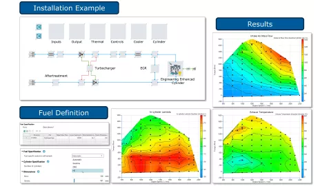
Engineering Enhanced Cylinder Model for Hydrogen Combustion and Emission
The combustion of hydrogen in conventional combustion engines could contribute significantly to the decarbonization of mobility, especially in the heavy-duty sector, provided that sufficient hydrogen can be made available at acceptable costs and the associated technical challenges can be resolved.
To help finding solutions for the latter, AVL CRUISE™ M 2025 R1 addresses the demand to simulate hydrogen-fueled ICEs with a dedicated model that extends the family of Engineering Enhanced (EE) diesel and gasoline cylinder components. This implies that the new H2 combustion and emission model follows the philosophy of combining basic thermodynamic principles with data-driven approaches in a semi-empirical manner.
The performance of the new EE H2 combustion model is also demonstrated by a new installation model. This model’s parameterization is inspired by hydrogen engine benchmarks at AVL.
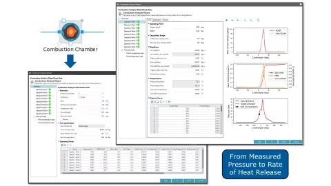
Combustion Analysis Wizard
Combustion analysis is essential to assess the complex thermodynamic process taking place in internal combustion engines. AVL Gas exchange and Combustion Analysis (GCA) provides this functionality online with AVL IndiCom™ and offline with AVL CONCERTO™. BURN, as part of AVL BOOST™, also offered this capability.
With this release, the high-pressure cycle combustion analysis, is also made available with CRUISE M directly alongside its engine thermodynamic simulation. A wizard guides you through a parameterization process considering the given cycle type, cylinder geometry, fuel properties, wall temperatures and heat transfer information, air and fuel mass flows, and most importantly, the high-pressure curves for an arbitrary number of engine operating points. Upon completion of the inputs the software generates ROHR curves and calculates the mass fraction burned as a function of crank angle. Additional results such as energy balance, mass fraction burned points and performance (IMEP, FMEP, etc.) provide feedback about the quality of the fitting. Good to know: the fitting process can be launched also for multiple operating points at once.
Engine Thermodynamics Enhancements
CRUISE M’s thermodynamic domain is the basis for all kinds of simulations around developing and improving internal combustion engines. Driven by the feedback from its users, several enhancements are made to the software with every new release to further improve usability, performance and applicability.
AVL FIRE™ M
ECFM-3Z New Developments and Enhancements
With the introduction of AVL FIRE™ M 2025 R1 the AVL ECFM-3Z Model got again upgraded. During the past development cycles, it has emerged as a robust and reliable combustion model not only for hydrocarbon (HC) -based fuels, but also for carbon-free hydrogen and mixtures of the former and the latter. 2025 R1 features:
-
Oxygen containing fuels
The ECFM-3Z model has been extended to account for the oxygen content oxygenated fuels, e.g. CH3OH, during combustion simulation.
-
Livengood-Wu Knock Model
The Livengood-Wu knock model is made available in combination with the ECFM-3Z combustion model. It is used to predict auto-ignition by assuming that the global reaction rate depends only on the unburnt thermodynamic condition and can be approximated by the reciprocal of the total ignition delay at a given temperature and pressure.
-
Apps for Auto Ignition Delay and Laminar Flame Speed Tables
The apps for creating auto ignition delay and laminar flame speed tables have been updated and two new apps have been introduced, enabling the visualization of both data sets and thus providing a simple possibility to check data for plausibility.
General Gas Phase Reactions
An improvement for FIRE M users who prefer modeling combustion by using the General Gas Phase Reaction Module is provided with a Python-based command line tool, which allows to easily reduce complex reaction mechanisms. The reduction helps to minimize the mechanisms' size, thus avoiding the need for excessive computational resources for combustion simulations.
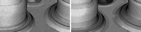
IC-Engine Model Generation
FIRE M Engine, our automated workflow to generate computational models for in-cylinder flow simulations, now offers the possibility to generate hexahedron-dominated grids in addition to the already well-known polyhedral grids.
This offer is aimed at users of our software who have previously deployed Fame Engine Plus to generate engine models. The ability to now generate hex-dominant meshes in FIRE M Engine allows these clients to continue to leverage their previously gained experience and eliminates the need to compare with polyhedral-based models.
AVL EXCITE™ M
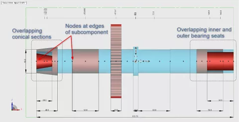
Free Definition of Shaft Inner Layout
A new possibility has been introduced for shafts that allows free and independent definition for inner and outer shaft geometry. Previously, only simple bores were possible at both sides of the shaft. With this extension, in addition to bores, any other appropriate body subcomponent can now be added to inner shaft geometry, which now also has a dedicated layout table.
The improved way of shaft modeling provides more accurate results for mass and inertia calculations when inner and outer sections overlap, even in cases when conical geometries are used. For frustums, arbitrary node configurations are now possible. Additionally, the node configurations now allow nodes on edges of subcomponents, which is important in certain applications.
Since the improved shaft modeling slightly changes simulation results to enhance accuracy, a compatibility switch has been added. It allows you to turn off the improved shaft modeling in cases where maintaining result consistency with previous versions is of higher priority than achieving higher accuracy.
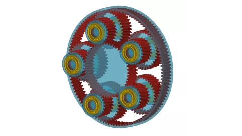
Stepped Planetary Gearset
The predefined assembly for the Planetary Gearset now supports stepped planets. When switching to this new configuration, the user interface automatically adds a second gear and a second bearing to the planets. All related joints between the sun, ring, carrier and planets are reconnected automatically. Additionally, all bodies are rotated and repositioned.
You are notified via data checks if the gearset cannot be assembled due to the given geometry. This informs you about the possible number of planets and the required phasing angles between the main and second gear for each planet.
Moreover, you now have the option to specify whether the bearings for the planets are mounted on a planet pin or directly into the carrier.
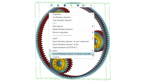
Conversion of Predefined Assemblies Into Generic Assemblies
It is now possible to convert predefined assemblies, such as the Planetary Gearset or the ICE Engine Assembly, into generic assemblies. This enables you to freely modify the assembly's topology to achieve unsupported configurations or address specific use cases. However, assembly specific configuration settings are no longer available for generic assemblies, and they cannot be reverted to predefined assemblies.
Consideration of Pitch Error for Spline Gear Connections
The inner and outer spline gear subcomponents of the spline gear joint now support defining a pitch error to accommodate manufacturing allowances. Three options to define the pitch error are available:
- Single pitch deviation
- Cumulative pitch deviation
- Definition via harmonic functions
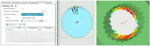
The pitch error can be specified individually for each flank side or as a common error for both flank sides. Additionally, a visualization scaling factor is available to amplify the error in the geometry visualization without affecting the error during simulation. Finally, during the simulation, the pitch error is overlaid with any defined microgeometry and any misalignments, such as tilting, that may occur.
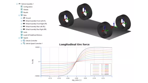
Simple Vehicle Model for Driveline and Transmission Applications
A 1D longitudinal vehicle representation has been implemented in AVL EXCITE™ M to model vehicle, tire and road influence on the powertrain targeting torsional vibration.
It includes front, rear, and all wheel drive configurations, vehicle mass with longitudinal degrees of freedom, and loads such as rolling resistance, aerodynamic drag, and road slope. The model features a Magic Formula tire model (Pacejka) with TIR file support and road grip ratio for each side. You can define target speed profiles and utilize a speed controller with internal/external definitions.
The vehicle model is primarily intended for gearbox and driveline applications to represent realistic boundary conditions imposed by the vehicle like impact of damping due to tire slip or sudden load changes due to varying road traction to be considered.
Bearing Lifetime Calculation App Extended Functionality
In addition to the existing ISO 16281 profile definition, you can now define roller profiles for cylindrical elements using data sets. Profiles can be specified in absolute units or as dimensionless values that can be applied to different bearing geometries. These profiles can be entered via a tabular interface or imported as CSV files. The operating temperature of the bearing lubricant can now be defined for each case, offering greater control over case inputs, particularly for accumulated lifetime calculations. Lifetime results for individual cases are now available in AVL IMPRESS™ M. These can be accessed within the case results for the selected bearing.
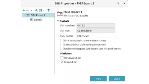
Export AVL EXCITE™ M Model as Co Simulation FMU
A new FMU Export interface component is introduced in EXCITE M. With this component, it is possible to export an EXCITE M model as a co simulation FMU. By executing the corresponding task, all required data and the necessary binaries for the solver are collected and packed into the final FMU ZIP file. The FMU can then be imported into any tool supporting the FMI 2.0 standard to perform a co simulation with EXCITE M. No full EXCITE M installation is required, only a valid license at runtime.
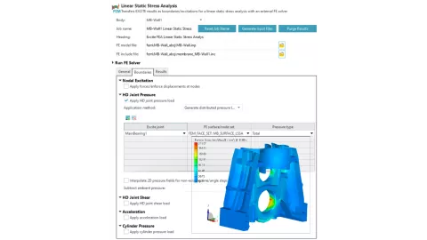
Support of HD Joints in AVL EXCITE™ M FE Tasks
HD joints (EHD2, EPIL and AXHD) are now supported in the Linear Static Stress Analysis app for pressure and shear application and in the Thermal Load Generator app for thermal load application. The Linear Static Stress Analysis app is available via the App Library inside EXCITE M, while the Thermal Load Generator app is available in COMPOSE. The Thermal Load Generator app is used in a workflow together with the EXCITE M model app and optionally with the Run FE Solver app if you want to have FE solver results in the same workflow run.
Component Modeler: Membrane Mesher
EXCITE M Component Modeler's Membrane Mesher feature generates regular membrane meshes that are required in modeling surface contacts within "hydrodynamic" joints: Advanced Radial Slider Bearing (EHD2), Advanced Axial Slider Bearing (AXHD) or Advanced Sliding Guide (EPIL).
Created membranes are "glued" (coupled with a surface based tie constraint or glued contact) to typically irregular FE meshes of, for example, a bearing housing, a piston skirt or a cylinder liner. In this way, the joint's hydrodynamic mesh will be in contact with regular FE meshes of connected bodies. The end result would be more reliable joint results.
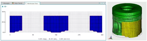
The current release contains the initial implementation of the Membrane Mesher feature. Membrane geometry (consisting of lines, rectangular and polygon patches) is defined "manually" by entering the geometry of the corresponding membrane patches. The feature currently supports condensation of FE models with "glued" membranes for the Abaqus solver. Support for other FE solvers (Ansys, Nastran, PERMAS, OptiStruct) is planned for subsequent releases.
Wear Modeling: Automatic Surface Roughness Updates
Previously, roughness could only be defined at the start of a simulation and remains the same for each grid cell, independent of wear that may occur. By enabling this new interpolated approach based on the wear depth, roughness can now be defined independently of surface patches, allowing each grid cell to be updated over longer periods of simulation time, such as when using the wear apps.
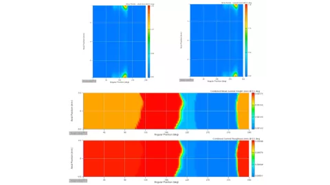
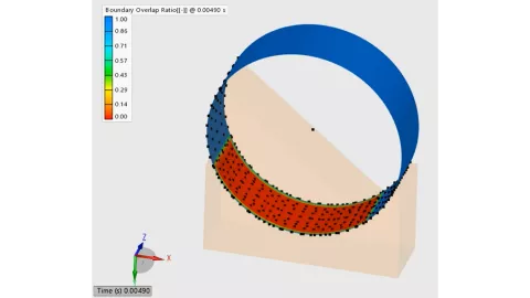
Simulation of Open Shell/Journal Surfaces in EHD Joints
There are several use cases for radial slider bearings where both contact bodies are not in full contact in the circumferential direction. Previously, the EXCITE solver only supported a closed contact or an open closed contact. The new implementation enables simulation of radial slider contacts with open journal/shell surfaces, such as those found in roller shoe or piston pin/piston boss bearings. This implementation is further supported by automatic boundary condition detection for open open contacts in the solver.
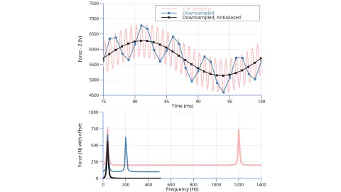
Anti Aliasing Filter for Downsampled Output Data
The EXCITE solver offers the option to downsample simulation data to a reduced output frequency, significantly reducing the size of output files for large simulations and parameter studies. However, when components exceeding a frequency of half the inverse of the output time step (Nyquist frequency) are significant, downsampling introduces aliasing artifacts. These artifacts can now be suppressed by having the EXCITE M solver apply an anti aliasing filter prior to writing the output data.
AVL Electric Motor Tool
MFC-Based Model for Induction Motor
The MFC-based model offers a fast solution for accurate dynamic and acoustic analysis of electric drives incorporating induction motors. By providing a simplified yet effective representation of the motor, this model enables engineers to investigate the impact of various operating conditions and the influence of Pulse-Width Modulation (PWM) on high-frequency content.
The theoretical background of the method, including validation with direct magnetic field computation, was presented at scientific conferences and published in proceedings.
One of the primary advantages of the MFC-based model is the ability to account for the complex interactions between the inverter, controller and machine, including the effects of switching patterns and harmonics. This level of detail is crucial for accurately predicting motor behavior under dynamic conditions, as well as predicting motor, control and PWM harmonics in quasi-stationary operation.
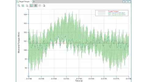
While the MFC-based model offers significant computational efficiency gains compared to direct field computation, it is resource-intensive in terms of primary and secondary memory.
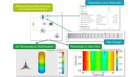
Cylindrical Cell – Multi Physical and Multi Dimensional Model
AVL CRUISE™ M offers a new Cylindrical Cell component that features a scope known from FE/CFD codes while maintaining the ease of use known from system level simulation. The usage of the Cylindrical Cell component is straightforward. At the top level, you can choose between an electrical equivalent circuit model or an Electrochemical, Pseudo-2D (P2D) model, and you can opt for guided or user defined geometry configuration.
The cylindrical cell model, roughly speaking, combines multiple physical models and geometrical dimensions. The thermal behavior is calculated in 3D, the potential distribution over the collector plates is calculated in 2D (think of an unrolled jelly roll), and between the collector plates, there are multiple P2D (or equivalent circuit) unit cell models.
Another important feature is the design of the collector tabs. You can size and position them according to your ideas and simulate the impact of current and temperature distribution on cell performance. These distributions can be analyzed via 3D postprocessing functionalities in addition to the conventional time based results known from the P2D cell model.
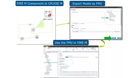
AVL FIRE™ M Battery – Seamless Model Export From System to CFD
This version of CRUISE M and AVL FIRE™ M offers a dedicated workflow to export any kind of Electrochemical Battery model from CRUISE M for import into FIRE M. The workflow starts with setting up an Electrochemical Battery model in CRUISE M. Once this is done, you pull a new dedicated FIRE M Battery component from the Export Interface Library. This component serves as an interface and guides you through a list of required data bus channels to establish correct physical causalities. With that you export the model following the CMC process to create an FMU which can then be loaded into FIRE M’s Battery module as a new model type, ready to be used in the context of CFD based 3D simulations.
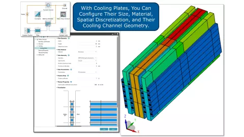
Battery Module – Cooling Plates
The design of battery modules is strongly driven by thermal aspects. There are multiple options to dissipate the heat generated by the battery cells into a thermoregulation network. CRUISE M addresses these design questions with the help of its generic flow networks and directly within the Battery Module component.
With this version of CRUISE M, you have access to one more type of stack element, namely actively cooled plates. When opting for cooling plates, you can configure their size, material, spatial discretization and cooling channel geometry. It can be of type rectangular with or without micro fins, or of type multi port extruded for rectangular or circular tubes. After running a simulation, 3D results on the temperature distribution over the entire module allow you to efficiently assess the impact of different cooling plate configurations.
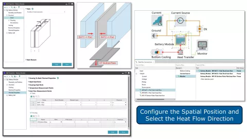
Battery Module – Heat Flow Monitoring
CRUISE M’s Battery Module component for pouch cells simulates 3D temperature distributions of individual cells, cooling plates, housing wall, etc., depending on the electrical load and the chosen thermoregulation concept. This version of CRUISE M allows you to assess these important thermal aspects more in depth with the help of new monitoring channels. In addition to the possibility to place temperature sensor channels, you can now also monitor heat flows.
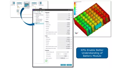
Battery Module – KPI Values
The configuration of a battery module full of pouch or cylindrical cells is typically done with the goal of reaching certain electrical KPIs like capacity or voltage. Besides that, there are several additional KPIs that are as important for design decisions. These are the module's length, width and height, its total volume, and the volumes and masses of a single cell, the cooling tubes, the packaging, the housing, and others. With this version of CRUISE M, all these quantities are available on additional KPI pages of the Module and Module – Cylindrical component.
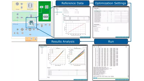
PEM Electrolyzer Stack Wizard
Model parameterization based on reference data is an essential step in any simulation project. This can turn into a cumbersome task that requires a thorough understanding of the underlying model, often featuring non-linear responses and parameter cross-sensitivities.
With the new PEM Electrolyzer Stack Wizard, AVL CRUISE™ M offers a shortcut to the often manually performed electrolyzer model parameterization task. The wizard can be launched from the Efficiency Portal or from the context menu of the PEM Electrolyzer Stack component.
When opening the first page of the wizard you are guided through four simple steps. First, you are asked to provide reference data, either from steady-state or transient operation, followed by a selection of parameters to be optimized. With that, you can launch the optimization process and finally inspect the fitting quality by different kinds of parity plots. When closing the wizard, all the parameters are transferred to the underlying PEM Electrolyzer Stack model.
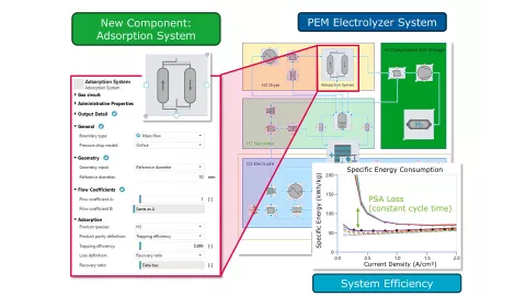
Pressure Swing Adsorber Model
Electrolyzer systems aim to produce hydrogen with a maximum level of purity, very often achieved via adoption of a Pressure Swing Adsorbers (PSAs). In this application, the separation of unwanted water vapor from hydrogen is accomplished using two or more adsorption vessels. While one vessel is pressurized to adsorb vapor, the other releases hydrogen with higher purity, followed by a purge step to get the adsorbed water out. Both vessels operate cyclically to constitute a pseudo-continuous process.
CRUISE M fully supports modelling of this process both with the help of its component library, and by offering a mean-value-based representation featuring high computational performance, namely, the new Adsorption System component. With this, the separation of components is modeled using an empirical approach where you can configure system performance, i.e. outlet purity and trapping efficiency. Similarly, you can specify losses of the product species, i.e. loss ratio, loss flow rate or recovery ratio, and different options to configure the connecting pins offer flexibility to invoke the component at any place of your system model. The "adsorbed" species leave the component via a dedicated waste pin, while purified gas exits via the product pin.
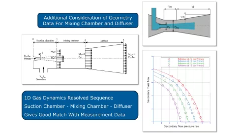
Advanced Venturi Injector Model
Venturi injectors are typically used on the anode side of fuel cell Balance of Plants (BoP) as an energy-efficient alternative to compressors. The primary side of the injector is typically connected to the high-pressure hydrogen tank (featuring pressures of several hundred bars), while the secondary side represents a recirculation flow from fuel cell exhausts, containing a certain share of unconverted hydrogen.
In this version of CRUISE M, the existing Venturi Injector component offers a new advanced model option. The advanced model balances the governing one-dimensional equations of compressible flow for separate sections of the suction, mixing chamber and diffusor. Importantly, the model approach is also affected by the outlet conditions (i.e., downstream pressure) under the limit of forward flow. To run the advanced model, you simply select the corresponding check box in the Venturi Injector component and specify the lengths of the mixing chamber and diffusor. Comparisons to experimental data showed a good match, which will further facilitate the parameterization effort due to its broadened physical basis.
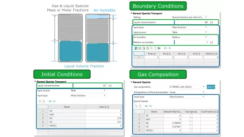
Liquid Volume Fraction Boundary Conditions
Modeling fuel cell and electrolyzer systems involves the transport of gaseous and liquid species. CRUISE M’s gas path supports the transport of species in both phases. This version of CRUISE M offers a new option to directly input the liquid volume fraction as an initial condition in the Plenum and various Fuel Cell Stack and BoP components, and as a boundary condition in the System Boundary, Mass Flow Boundary and Volume Flow Boundary components. Once you specify a certain liquid volume fraction, CRUISE M calculates the remaining gas volume, following the provided mass or mole fraction table. If you opt for the specification of humid air, as offered by the different boundary condition components, it is part of the gas phase, in addition to the setting of the liquid fraction.
Simplified Fuel Cell and Electrolyzer Model
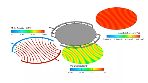
A new feature has been introduced in AVL FIRE™ M, allowing you to quickly adjust numerical settings for both electrolyzer and fuel cell configurations. This feature, combined with heat and mass sources, enables you to set up simplified models for fuel cells and electrolyzers with ease. This update allows for the calculation of only the cathode or anode, using simplified mass and heat sources for more efficient simulations. Additionally, you can choose to calculate either the gas channels only or to include the Gas Diffusion Layer (GDL) and catalyst layer in your simulations as well. In the figure below, half of the PEM electrolyzer was modelled to ensure a swift calculation of the electrolyzer, so the user can have results in very short time.
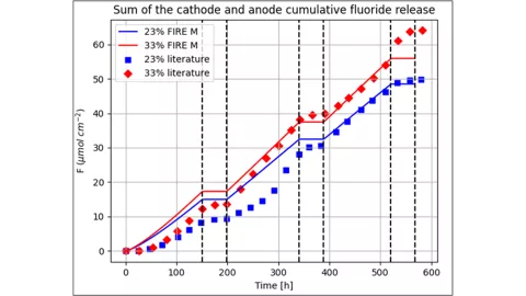
PEM Fuel Cell Chemical Membrane Degradation Model Validation
The chemical ionomer degradation model of FIRE M has been further validated by comparing simulated membrane degradation characteristics to the corresponding experimental data. During chemical ionomer degradation, the unwanted transport of oxygen across the membrane leads to the formation of hydrogen peroxide (H2O2) in the anode catalyst layer and, consequently, to the production of OH radicals via the reaction of H2O2 with metal ions. The OH radicals attack the side and main chains of the ionomer leading to the reduction of the ionic conductivity and thinning of the membrane. As a side product during the ionomer attack, hydrogen fluoride is produced, transported towards the flow channels and flushed out of the cell. The hydrogen fluoride release can be measured and, thus, ionomer degradation can be detected and quantified indirectly. The figure below clearly shows that the general trend of a higher amount of fluoride for the larger ionomer volume fraction can be predicted by the simulation with high precision.
We are excited to announce the joint solution by AVL and Persival, bringing a groundbreaking advancement for virtual testing and validation of Advanced Driver Assistance Systems (ADAS) and Autonomous Driving (AD).
New NCAP Regulations
The Euro NCAP has recently introduced its first regulations that specify virtual testing with qualified simulation models. These regulations, effective from January 2026, focus on Safe Driving and Crash Avoidance. They outline stringent qualification criteria for simulation models, including the need for in-house validation by OEMs and physical verification by Euro NCAP. The regulations emphasize the importance of accurate simulation models and their validation to ensure that virtual testing results are credible and can be trusted for regulatory compliance. By aligning with these new regulations, the joint solution by AVL and Persival ensures that customers are well-prepared to meet industry requirements and advance their ADAS and AD vehicle testing processes.
Comprehensive Simulation Model Validation and Credible Simulation Processes
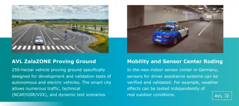
A key highlight of this joint solution is the comprehensive methodology for simulation model validation using real-world measurements. This is where AVL's unparalleled expertise and infrastructure come into play. With access to state-of-the-art facilities such as the Roding Weather Hall and the ZalaZONE Proving Ground, we offer a full solution that encompasses both virtual and physical testing environments.
This combination ensures that simulation models are thoroughly validated, leading to more accurate and reliable results. AVL already offers a market-leading solution for validated vehicle dynamics simulation with up to 97% model correlation. Validating sensor models with real measurements is crucial to fulfill the new NCAP regulations and ensure that simulation results are reliable and trustworthy. We offer a combined solution with a full service offering that includes real world measurement campaigns on proving grounds, model parametrization and validation as well as integration of ADAS/AD software.
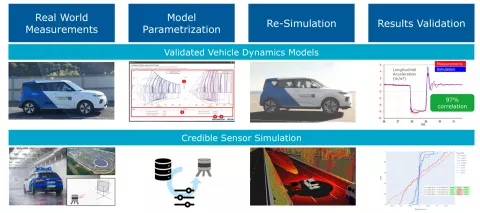
Scenario-based testing is then performed on real and virtual proving grounds based on test specifications in ASAM OpenSCENARIO standard. The test results are verified for regulatory compliant test execution and then also rated based on safety metrics and KPIs. Significant cost and time savings are possible by shifting tests into the real world in a systematic way that ensures trustworthy and reliable results.
Seamless Sensor Simulation Integration
The integration of Persival's sensor simulation models into the AVL Scenario Simulator™ is seamless thanks to the ASAM Open Simulation Interface (OSI) standard. This ensures a modular and scalable simulation environment, utilizing complex models where necessary. The effortless integration and replacement of models save significant integration effort, allowing our customers to focus on innovation and development. Whenever scenarios cannot be handled with simple object-level models, they can be easily replaced by dedicated, high-fidelity sensor models that cover multiple physical effects and leverage GPUs (Graphic Processor Units) for high-performance execution. With this unique modular approach, it is even possible to couple the original signal processing from the sensor manufacturer as a black-box model to achieve a full digital twin of the sensor, ensuring the highest credibility possible.
We believe that the joint solution by AVL and Persival marks a significant step forward in the development and testing of ADAS and AD vehicles. This solution underscores our commitment to providing cutting-edge technologies that meet the evolving needs of our customers. In combination with high quality 3D environments and objects based on the ASAM OpenMATERIAL 3D standard, credible sensor simulation at scale now becomes reality.
AVL VSM™ Unveils Snow Simulation for Winter Testing, Automatic Virtual Driver Parametrization, and Enhanced Post-Processing Options.
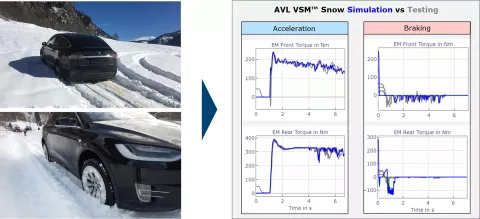
Advanced Snow Simulation for Winter Testing
Vehicle manufacturers and suppliers invest significant time and resources into test trips, and need to wait the winter season to calibrate, test their vehicles, and validate control systems in cold-weather and snow conditions. These trips often involve complex logistics, high costs for staff travelling, and time-consuming methods. It's often the case that a test trip needs to be extended due to change on weather conditions or unforeseen testing requirements.
The interaction between all tires and snow is considered in the new AVL VSM™ for both steady-state and transient maneuvers, ensuring a high model fidelity. This new feature builds trust in the calibration of controls, driving strategies, and test cases such as hill climbing and towing a trailer, among others. The parametrization of winter/all season tires and snow properties are essential for ensuring efficient calibration methods and driving experience.
With new VSM 2025 R1 snow simulation feature including templates, much of this effort can now be significantly reduced. By accurately simulating winter conditions in a controlled and reproducible environment, our solution enables OEMs and suppliers to conduct critical vehicle and control system tests and calibration in the office, testbeds or driving simulators without the need to wait for the winter period, improving efficiency, quality, reducing costs, and accelerating development timelines.
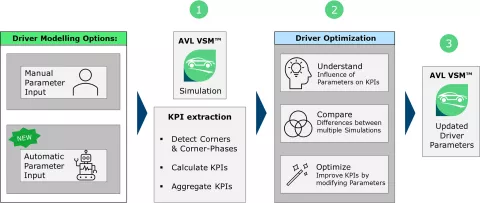
Automatic Parametrization of Virtual Driver
High performance driver models are essential for simulating vehicle lap time and handling, but they require parameter fine-tuning to push the complete vehicle to the limit as in real life. Tuning driver models normally requires expert knowledge and interactive loops, to ensure the driver’s actions align with the vehicle's capabilities and track conditions. For effective calibration, parameters such as vehicle weight, tire characteristics, powertrain performance, and track conditions like path, tarmac grip and banking must be accounted to achieve a realistic simulation result.
To simplify and accelerate this process, AVL developed an automatic driver parametrization feature that optimizes the driver model by considering any changes done on both vehicle and track level. As such, VSM ensures that the driver model is optimized to extract the maximum possible performance. This significantly reduces the time and effort required to tune the model and improves overall simulation accuracy and comparability, enabling better decision-making for hardware and control strategies.
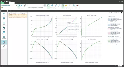
New AVL VSM™ Simulation/Testing Post-processing
The use of pre-defined graphs and plots for virtual testing post-processing enables VSM users to quickly analyze results, make faster and more informed decisions, and generate reports within minutes. A set of pre-configured examples that users can directly apply to analyze and compare their simulation results streamlines post-processing. These post-processing templates can be customized to accommodate various analysis scenarios, helping users save both time and costs during the development of vehicle models and the investigation of different virtual test results.
Release 2022 R2
- Virtual System Development - Concept, Layout and Integration
- Virtual Function Development - Automated and Connected Mobility
- Virtual Battery Development - From Cell to Vehicle
- Virtual Fuel Cell Development - Components and Systems
- Virtual Driveline Development - Transmission and E-Drive
- Virtual ICE Development - Durability and NVH
- Virtual ICE Development - Performance and Emissions
Stay tuned
Don't miss the Simulation blog series. Sign up today and stay informed!
Stay tuned for the Simulation Blog
Subscribe and don‘t miss new posts.