
Rolling Element Bearings - Damping in Clearance Regime
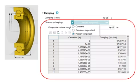
For Rolling Element Bearings, in the currently applied approach, the material contacts accounts for damping while the damping which is expected in the clearance regime is not considered. To stabilize the bearing behaviour in the clearance region, additional damping forces is acting in the gap region of the individual contacts. The required damping coefficients are specified as a table depending on the contact approach distance.
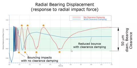
The following graph shows the bearing radial displacement as the response to a bearing impact load. While the bearing without any clearance damping reveals repeated bouncing within the radial play, the variant with clearance damping is characterized by a smoother decay.
Deviation/Tolerance Input for Spline Gear Joint
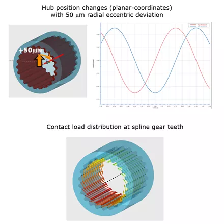
Geometric deviations from nominal drawing dimensions may have a significant impact on the NVH performance of transmissions and Electric Drive Units. To consider deviations that cause eccentricity of components, the Spline Gear joint has been extended to process axial, radial and angular deviation inputs given at the shaft/hub link locations defining the body-spline profiles of the connection. The figure shows the impact of a radial deviation of the outer spline profile against the axis of rotation of a shaft. The radial hub motion follows the run-out of the shaft-spline leading to periodic position changes associated to radial force fluctuation in the spline-gear interface.
Spline Gears: Offer Crowning via Microgeometry
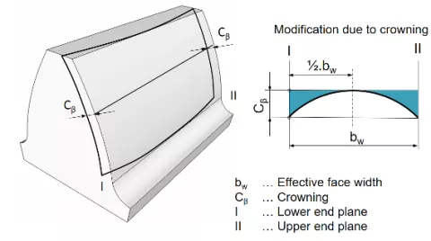
For certain use cases of splined gears, it is essential that only the torque, but no bending moment is transferred from one shaft to another. This is achieved by applying a crowning modification to the flank surface across the width of the gear. Crowning can now be specified on the outer (shaft) and inner (hub) side of the spline gear contact. The modification is visualized in the 3D-viewer and IMPRESS M.
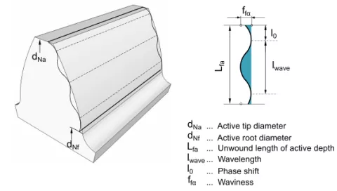
Cylindrical Gears: Offer Flank Surface Waviness Modification
Manufacturing of the gear grinding process cause various imperfections of the resulting flank surface which can have a significant impact on the gear noise. One prominent deviation pattern is called waviness. Waviness along the gear tooth can now be specified on cylindrical gears and is considered by the contact model.
New Method to Consider Localized Gear Wheel Body Node Deflections at Tooth Contact (Beta)
Advanced Cylindrical Gear Joint has been able to consider flexible gear wheel body deflections from circumferential nodes placed at the root of the teeth. However, the applied mapping method performs some averaging that causes specific gear wheel body deflection shapes (for instance the well-known "potato-chip" mode), not sufficiently reflected in the contact-load distribution between the individual teeth. A new mapping method that considers body deflections affected by the gear contact has been implemented optionally. Using this option, local body modes will influence the development of the gear contact pattern in a much more realistic way.
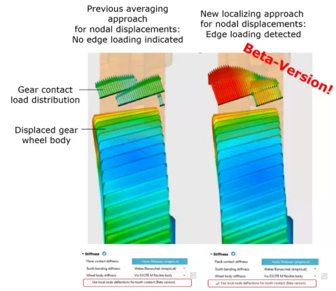
New method is more prone to dynamic loss of flank contact and it is more sensitive to numerical instabilities of the time domain solution. Therefore, for 2023 R1 the feature is released as a beta version. To activate it select "Use local node deflections for tooth contact (Beta version)" check box in ACYG "Joint properties | Stiffness".
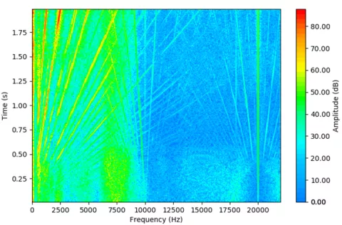
Pulse Width Modulator
Pulse Width Modulation (PWM) realizes the variable magnitude and variable frequency voltage demand calculated by the current controller. The pulses control the switches of the inverter. The pulsed voltage introduces considerably higher harmonics into the torque and the forces acting on the electric motor's stator and thus contributes to e-motor NVH. EXCITE M now makes it possible to investigate the effects of PWM to avoid tonal excitations in regard to PWM strategies, overmodulation, use of constant or a speed-dependent switching frequency or a band for a random switching frequency as sown in the figure.
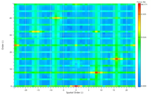
Order Analysis for E-Motor Tooth Forces
Force excitation of the stator teeth in an electric motor is best described by waves propagating with and opposite to direction of rotation. Due to the nonlinearity of the magnetic field spatial wave numbers will occur at base and harmonic frequencies. The analysis of their amplitudes and phases provides valuable indicators for an acoustic analysis. 2D-order analysis is now provided for all electric motor models with circumferential link locations for the stator. Each linking section is evaluated separately, which allows the study of impact of skewing, eccentricity and tilting of the rotor. Impact of pulse-width modulation can also be captured by narrow-band analysis.
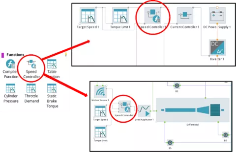
New Generic Speed Controller
A new generic speed controller component is introduced in EXCITE M. This speed controller replaces the internal speed controller of the Electric Machine Controller but is also available as a generic standalone component for other use cases. The controller is a PI-controller, where controller gains and initial states can be user-defined or automatically calculated based on control parameters (rise time and percentage overshoot), and model-specific parameters (effective moment of inertia and effective rotational damping).
The controller is implemented as a specialized version of the compiled function component. Due to this approach, it is also possible to convert the speed controller to a regular compiled function component for custom modifications like changing signals, parameters or even the actual controller code.
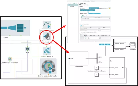
Direct MATLAB® Interface
The MATLAB® interface component enables a co-simulation between EXCITE M and MATLAB®/Simulink®. The interface is fully integrated into the signal network, allowing connections to sensors, functions (compiled function, tables, etc.), load applicators or other interfaces. Input and output signals can be defined for arbitrary physical quantities and additional parameters for the Simulink® model. Currently, MATLAB® versions up to R2021b are supported.
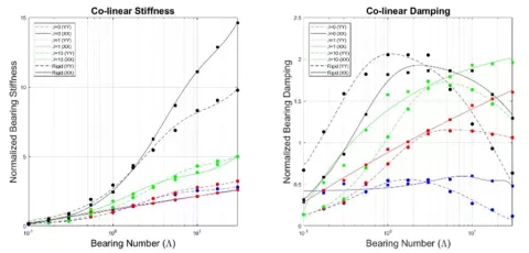
Map-Based Air Bearing Joints
Air bearings are commonly used in turbomachinery and fuel cells, so a simple way to simulate both axial and radial air bearings is required. Bearing maps plotting the normalized stiffness and normalized damping against the bearing number, such as those shown in Figure below, can be used for this purpose as an input.
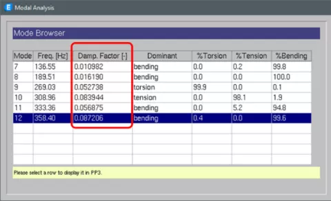
Damped Modal Analysis of Crankshafts and Rotors in AVL EXCITE™ Designer
In EXCITE Designer, the damped modal analysis is extended to the shaft modeler to cover the crankshaft and plain shafts (e.g. rotor). It is possible to perform the damped modal analysis of a free or an elastically supported crankshaft considering the damping in torsional vibration damper, main bearings and the crankshaft structure.
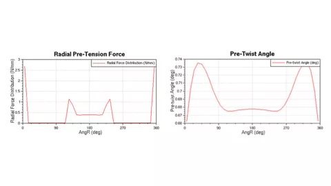
Calculation of Ring Preload Due to Ring Assembly in AVL EXCITE™ Piston&Rings
The calculation of the ring preloading condition due to the ring assembly deformation could be difficult or time consuming. Often only the ring open geometry is known. In this case, the ring conformability workflow allows the calculation of ring preloading conditions by considering the ring open geometry and fitting it into the liner shape. The conformability calculation provides results about ring radial pre-tension and pre-twist angle.
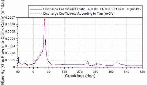
Analytic Gas Flow Discharge Coefficients for Ring End Gaps
Calibration of the gas flow coefficients can be very time-consuming and require multiple iterations to achieve the desired results. The gas flow coefficients are usually static values found through calibration against physical testing, which can be difficult when developing new fuel engines such as hydrogen given the current lack of physical testing results. The new analytic method for gas flow at the ring end gap is based on the work of Tian and is applicable for hydrogen, gasoline or diesel engine.
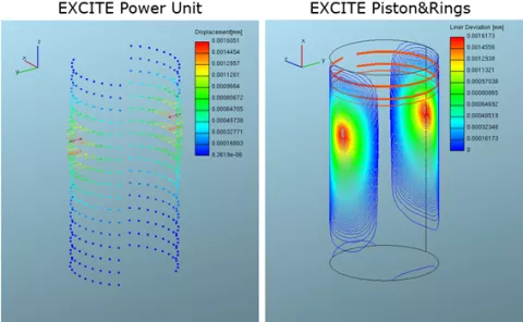
Liner Deformation Map from EXCITE™ Power Unit into EXCITE™ Piston&Rings
If the piston dynamics analysis is performed in EXCITE Power Unit, liner deformations due to piston slap are considered. On the other hand, in EXCITE Piston&Rings liner deformations due to piston - liner contact is not available. As a result of this limitation, if the piston secondary motion is imported from EXCITE Power Unit into EXCITE Piston&Rings, the piston may penetrate the liner shape, thus causing inaccuracies and simulation instabilities due to negative land volumes. For this reason, the possibility to store the liner deformation calculated via EXCITE Power Unit and import it into EXCITE Piston&Rings has been introduced. The map contains liner deformation values along the whole liner surface and for each result storage step. This workflow should be used when an external piston secondary motion is imported into EXCITE Piston&Rings.
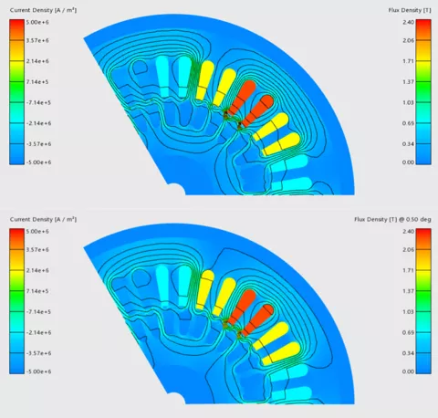
Map-Based (Tooth Force) Model for Induction Motors in AVL E-Motor Tool™
Induction motors are characterized by an inhomogeneous and varying current density in the rotor bars as well as pseudo-periodicity due to the slip between electrical and rotor frequency. Both impact stator tooth forces and thus e-motor NVH. The variable current density in the rotor bars require a transient simulation with a transient initiation phase that needs to wear-off to reach quasi-stationary operation. The automated workflow in EMT initializes the transient magnetic simulations in frequency domain, which strongly reduces the initiation phase. E-Motor Tool (EMT) offers an induction motor workflow to parameterize the map-based (tooth force)-model in EXCITE M.
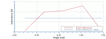
Upgrade of Inductance and Current Control Evaluation
EMT uses the maximum torque per ampere (MTPA)-strategy to evaluate the current table. It requires inductances of the motor to estimate torque and induced voltage using a fundamental wave model. Inductances in direct- and quadrature-axis vary with rotor angular position in an unrelated manner introducing uncertainty to the model fidelity. Furthermore, permanent magnet-flux linkage in quadrature direction and cross-coupling inductance may not be neglected under certain current excitations. EMT now samples inductance values over an angle range and averages the position-dependent values like in the standard measurements. Furthermore, pm-flux linkage in quadrature direction and cross-coupling inductance are evaluated and fed to an extended fundamental wave model.
In a next step EMT applies MTPA-strategy to evaluate the current tables. Special attention is put to the maximum torque line as it is most frequently used in dynamic and acoustic analysis. The algorithm is extended to generator operation mode as well as negative speeds to support all four quadrants of the operation range with accurate transition along the zero-torque line.