AVL Simulation Software Release 2025 R2
Published on November 03, 2025 · 5 min read


Vehicle System
Model Flow Diagram – Next Step in Model Assessment
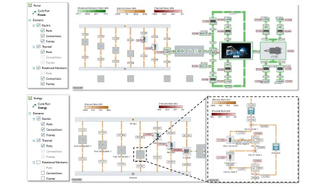
Multi-physical system simulation deals with the transport and conversion of energy in plants composed of components from gas, liquid, electrical and other domains. CRUISE M offers Sankey diagrams to analyze such systems. This version introduces Model Flow Diagrams (MFD), a unique tool to assess power and energy distributions. In contrast to the abstract visualization of Sankey diagrams, MFD visualizes power and energy fluxes as an overlay on the original block model. The fluxes are divided into those exchanged between components and those representing losses leaving a component. MFD visualizes data from different simulation time snapshots, assembled into a transient animation.
Profile Composition – Driving Range and Fuel Consumption
The transition to electrified mobility requires a shift from classical certification cycles to cycles that allow assessment of a vehicle's driving range or fuel consumption in a more comprehensive manner. In addition to CRUISE M’s Random Cycle Generator (random assembly of velocity profiles from a database of 20,000 profile snippets) and CRUISE M’s Route Generator (import of real velocity profiles from HERE.com), it is now also possible to compose driving profiles from CRUISE M's database of certification cycles. You do not need to do much more than pull the new Profile Composition component from the library and start configuring it. The component allows you to select from around 50 different certification cycles and compose them according to your needs. Define an arbitrary number of profiles and create a composition consisting of any sequence of your defined profiles.

Offset Strip Fin Heat Exchanger – Enhanced Heat Transfer Performance
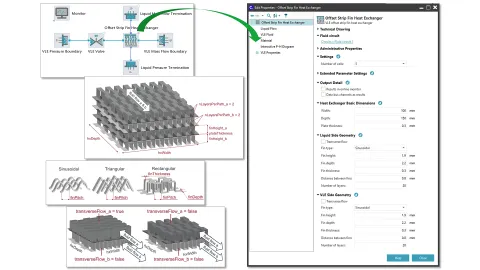
Heat exchangers featuring offset strips are one possible option to enhance heat transfer performance between air conditioning and liquid flow circuits. This version of CRUISE M introduces a component that supports exactly this type of heat exchanger. New heat transfer and pressure drop models dedicated to offset strip fin geometries extend the existing lists of correlations. You can explore the corresponding installation example to become familiar with the component and its advantages compared to conventional plate heat exchangers.
Battery System
Discretized Solid Cylinder 3D – Thermal Modeling Beyond Cuboids
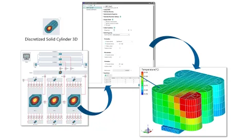
The assembly of cuboidal objects is one possible approach to model heat transfer in solid structures in 3D. CRUISE M’s Discretized Solid 3D component (DS-3D) supports this, augmented by a 3D Viewer that shows previews and allows interactive configuration of thermal connections. This version of CRUISE M introduces a new Discretized Solid Cylinder 3D component (DSC-3D). You can define different materials in the radial direction, configure a hollow inner radius and select between a full, half and quarter cylinder. Heat ports and measuring points help you apply heat sources and monitor temperatures at points of interest. The DS-3D and DSC-3D components model the geometry and temperature distribution within the jelly roll, as well as between its sections located in the prismatic and two half-cylinder parts of the cell.
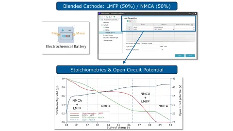
Electrochemical Battery – Heterogeneous Electrode Blends
Advanced designs of lithium-ion batteries combine the advantages of individual electrode materials. LMFP, as a blend of LFP and LMP, features the thermal stability of the former and the energy density of the latter. Classical electrochemical P2D models, which apply homogenized approaches, fail to model blends, as they cannot be described as a linear overlay of the contributing materials. To address questions on heterogeneous electrode designs more thoroughly, this version of CRUISE M introduces an extended and refactored Electrochemical Battery (ECB) component. The new ECB provides material-based inputs for cathode, anode, separator and electrolyte. You can configure different electrode materials and combine them as a blend applied over an entire electrode or just over one of multiple layers. Each material has its own settings and inputs for intercalation and degradation.
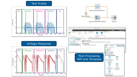
Battery Validation Protocol – From Test Profile to Report
The behavior of battery cells can be assessed in many ways. When examining test scenarios involving different loads, load dynamics, temperatures and more, it is easy to lose track and compromise comparability between tests. This version of CRUISE M introduces a structured approach to virtual battery testing with the new Battery Validation Protocol (BVP) component. The component includes time-based load profiles covering SOH checks, C-rate tests, pulses and a dynamic cycle profile, all at different operating temperatures. The protocol organizes individual test segments to minimize test time, and it is adjustable to different cell sizes and chemistries. A dedicated BVP Evaluation App condenses approximately 200 hours of simulated results into individual segments, showing data as a function of time and SOC, ready for custom analysis or presentation in predefined result pages.
Fuel Cell and Electrolyzer System
PEM Electrolyzer System Generator – Model Setup from One KPI
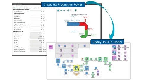
This version adds a new generator to CRUISE M that supports the setup of a Proton-Exchange Membrane Electrolyzer (PEMEL) Stack and Balance of Plant (BoP) model from a single stack input, along with optional information regarding BoP component efficiencies and operating point conditions. When you launch the PEMEL System Generator from the Efficiency Portal, you will also notice a newly introduced feedback functionality. Based on your input KPIs, you will receive initial estimates on expected system KPIs such as power losses and specific power consumption with respect to the stack or the whole system. There is also a Sankey diagram visualizing the power split from given electric power down to the produced hydrogen. Upon clicking the Finish button, you will receive a detailed BoP model including appropriately scaled separators, tanks, valves and other components, as well as monitors and controls to operate the complete system.
AEM Electrolyzer Stack – Performance Model
Anion Exchange Membrane (AEM) electrolyzers are considered a cost-efficient alternative to Proton Exchange Membrane (PEM) electrolyzers. AEMs feature the known power and efficiency of PEM systems while avoiding cost-intensive platinum group metals (PGM). In AEM electrolysis, the OH- hydroxide anion moves from the cathode through the membrane to the anode, leaving gaseous hydrogen at the former and producing oxygen at the latter. Based on that, this version of CRUISE M offers a new AEM Electrolyzer Stack component. The component allows you to choose between 1D and 2D resolution, configure geometry, pressure loss, electrochemical transport, thermal and reactant crossover models, and provides full access to all membrane material data. A new installation model shows a comparison between simulation and measurement using literature data for different KOH concentrations and further explores the sensitivity of the stack model to different operating conditions and electrolyte feed configurations.

Thermodynamics and Exhaust Aftertreatment System
Combustion Analysis Wizard – Mastering Thermodynamic Processes
The Combustion Analysis Wizard, which is the successor of BURN in AVL BOOST™, derives ROHR tables or VIBE parameters from measurements ready to model in-cylinder combustion in CRUISE M. The wizard guides you through a parameterization process considering the given cycle type, cylinder geometry, fuel properties, wall temperatures and heat transfers, air and fuel mass flows, and most importantly, the high‑pressure curves for an arbitrary number of engine operating points.
With this version of CRUISE M, the applicability of the wizard is enhanced in three areas.
Import of iFiles: iFiles can be seen as an industry standard for storing high-pressure cylinder traces. CRUISE M now supports the import of data from this file format.
Heat of evaporation: If you want to refine the quality of your combustion analysis, access to the heat of evaporation provides additional flexibility.
Summary page: When running the combustion analysis for a list of operating points, detailed result assessment requires stepping through individual cases. With this version, you can inspect global results on a common summary page.

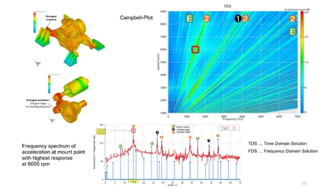
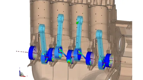
Enhanced Frequency Domain Solution (FDS)
The FDS is a simplified method used in early design steps for analyzing NVH behavior of gearbox systems and e-drives. It is limited to stationary operation and excludes non-linear properties of joints. The same AVL EXCITE™ M model can execute superior Time Domain Solution (TDS) or FDS enabling both detailed troubleshooting and early-stage NVH simulations.
FDS enhancements include:
- Kinetostatic Solution: higher accuracy and greater tolerance against unbalance of external loads.
- Gear Excitation: The Tooth Contact Analysis (TCA) is now based on the static equilibrium of the entire system and accounts for angular misalignments and tooth microgeometry.
- Electric Motor Excitation: are now considered for all available types of electric motor joints by assuming a stationary operating point of the underlying electrical network.
- Results: are now available for joints. Excitations from gears and electric motors are no longer handled as external forces/moments but are considered at the level of joint.
- Performance Improvements: gear TCA and electric motor joint force calculation now integrated directly into the solver reducing the time needed for preparing the excitations.
Efficient Storage and Navigation of Joint Results
All joint-related results have been fully migrated to the new HDF5-based storage format. With the new format, each component now has a single, unified result file. One of the top priorities was to eliminate confusion around result names.
With this release:
- Results now use the exact names defined during model setup and selection.
- Consistent naming conventions make it easier to locate and understand outputs.
- Logical grouping of results brings clarity and structure to the workflow.
The entire experience has been streamlined and more efficient:
- Fewer clicks to reach data thanks to a simplified, intuitive tree structure.
- Improved search integration.Faster simulation runtimes and reduced storage requirements.
- Selective output control: Choose exactly which joint results or body nodes to evaluate before the simulation starts.
Oil Supply Line (OSL) Network
The OSL network has been migrated from AVL EXCITE™ Power Unit to EXCITE M. The OSL is used to model oil flow between bearing systems, connecting multiple bearings via a structured network of oil lines.
The key features of the oil supply line network are as follows:
- Influence of Motion on OSL: Effects of rectilinear, centrifugal, Coriolis and Euler forces are considered, impacting pressure distribution due to system motion.
- Pipe Cavitation Modeling: Oil pressure drops leading to cavitation are evaluated, distinguishing OSL behavior from bearing gap cavitation.
- Configurable OSL Designs: Supports EHD2-type bearings with multiple topology options, including straight, T-line, I-line, double-I-line and multi-straight-line networks.
- Hydraulic Network Interaction: Multi-OSL configurations can interconnect, treating overlapping bores as coupled systems.
- Flow and Pressure Considerations: Accounts for friction loss (laminar/turbulent), viscosity dependence on pipe temperature, entry/exit pressure losses and mass conservation principles.
- Cavitation Detection and Evaluation: Identifies vaporization points along the line, assessing oil column separation and rejoining behavior.
- Pumping Effect Implementation: Models centrifugal force-induced oil transport within rotating components.
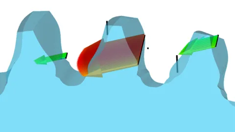
Extended Generic Contour Contact
Contour contact latest enhancement adds flexibility and realism by capturing nodal deformation and supporting multi-node contact behavior. Until now, contour joints were limited to one-on-one (single node) interactions. New capability supports single node to multi-node contact, delivering more accurate simulation results for complex geometries and flexible components. This release brings several key enhancements:
- Adaptive reference nodes for contour positioning
- Smarter contact force distribution across multiple nodes
- Evaluation of friction forces perpendicular to the contour plane

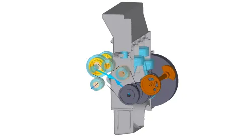
Enhanced Belt Drive Joint
The new belt drive joint now fully supports arbitrary global motion of the pulleys. This enhancement allows for accurate simulation of belt dynamics in scenarios involving significant global pulley movement, such as belt starter-generators or start-stop maneuvers.
The joint provides an intuitive visualization of belt spans in the user interface. The animation of the resulting pulley forces and moments is now available in the 3D animation of AVL IMPRESS™ M.
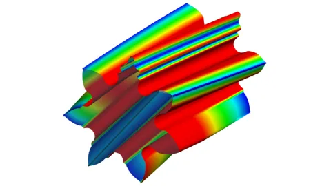
Advanced Microgeometry Definition for Cylindrical Gears
The microgeometry for the predefined modification type now supports an advanced definition option, providing greater flexibility in defining microgeometry. New capabilities include:
- Multiple Modification Instances: per modification type, each with independent parameters.
- Tooth-Specific Application: defined per tooth, offering greater design flexibility.
- Extended Waviness Definition:
- Now applicable in any direction on the tooth flank, not limited to the profile direction.
- Can be synchronized with the contact line direction.
- Allows definition of order along the engagement path.
These enhancements allow to model waviness caused by manufacturing tolerances or to explicitly design a contact-line-synchronized waviness that reduces gear mesh-specific excitations, targeting user-defined excitation orders.
SKF Rated Bearing Life for Rolling Element Bearings
The application now supports bearing lifetime prediction using SKF's cloud-based calculation service for SKF bearings. The SKF account registration provides access to the SKF online service. Besides the basic rating life L10, the specific SKF rating life L10m is also provided as a more encompassing method.

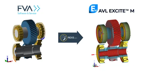
Enhanced REXS Import Functionality
The REXS import is improved by integrating the new shaft modeler capabilities and introducing additional customization options:
- Improved Shaft import enables a separation of inner and outer shaft layouts enhancing also the visualization of bores.
- Upper Stiffness Limits can now be defined as a threshold value. This helps mitigate issues caused by high stiffness values, often originating from ideal-stiff connections.
- Ignore Small Shaft Sections by specifying a minimum width threshold for shaft subcomponents. This helps avoid the creation of very small shaft sections.
- Floating Bearing Assembly option lets you automatically generate floating bearing assemblies simplifying model setup.
- Single Carrier Body enables us to merge all carrier-related components (e.g. side plates, pins, central shafts) into a single carrier body. All internal joints between these components are automatically removed to streamline the model and reduce complexity.

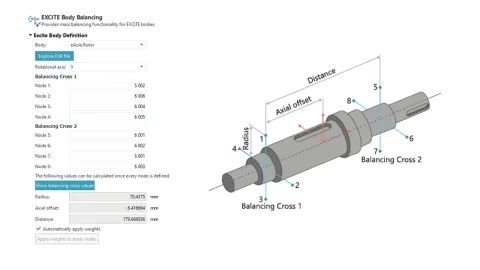
Body Balancing Application
Unbalances in rotating components lead to vibrations, bearing wear and material stress. In practice, almost all fast-rotating parts are balanced by counterweights added to the structure.
- Goal of Balancing: The mass distribution is adjusted so that:
- The center of mass lies on the axis of rotation
- The axis of inertia aligns with the axis of rotation
In most real-world cases, static and dynamic imbalances occur simultaneously, which is why both are corrected together. The Body Balancing App in EXCITE M performs balancing procedures automatically, ensuring full compensation of the unbalance.
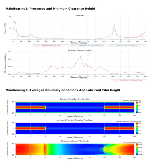
EHD Report Generation Application
MFC-Based Model for Induction Motor
A new application is now available to enhance postprocessing capabilities following EXCITE M simulations for advanced radial slider bearings (EHD2). This tool enables you to automatically generate standardized reports, similar to those previously available in EXCITE Power Unit.
Key features include:
- Seamless Integration: Available through the EXCITE M app library, ensuring easy access.
- Automated Report Generation: Creates reports in IMPRESS M and PowerPoint formats.
- Customizable Results: users can select scalar and postprocessed 2D.
- Comprehensive Data Representation:
- Averaged Results: Boundary condition, clearance height, fill ratio, lubricant film height, lubricant properties, lubricant temperature, pressure and thermal loads.
- Results at Maximum Total Pressure and Minimum Clearance Height: Clearance height, fill ratio, lubricant film height and pressures.
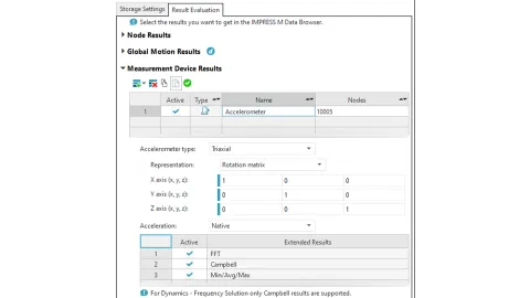
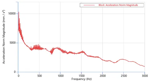
Virtual Accelerometer Improvements
The existing virtual accelerometer sensor results in EXCITE M have been extended with a triaxial type of accelerometer. Along with the sensor type, the orientation of the sensor can be defined as desired. It also reduces the amount of time needed to define the sensor in the model.
Empowering Smarter Engineering Decisions
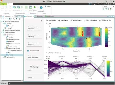
AVL EXPLORE™ brings simulation and test data to life, transforming it into actionable engineering insight. With powerful capabilities for surrogate model creation, design space exploration, optimization and digital twin development, EXPLORE helps engineers move from data to decisions faster and more effectively.
In today's fast-paced development environment, EXPLORE offers a lean, intuitive interface that handles machine learning behind the scenes, allowing you to focus on engineering outcomes. Fully integrated into the SDT ecosystem, it ensures a seamless and familiar experience. What you can do with EXPLORE:
- Replace time-intensive simulations with fast-running surrogate models.
- Explore design alternatives and evaluate trade-offs with ease.
- Optimize system performance using built-in algorithms.
- Create digital twins for predictive analysis.
- Export models as FMUs for integration into SDT supported workflows.
- Build surrogate models from simulation or test data.
- Optimize surrogate models to enhance performance EXPLORE is your go-to solution for turning complexity into clarity, making engineering insight more accessible than ever.
As with every release of AVL FIRE™ M software features and simulation capabilities are provided in response to recently seen and anticipated future technology trends in the mobility sector and other industries. With 2025 R2 a strong focus was set on providing new and enhanced simulation models for advancing the development of fuel cells and electrolyzers. For supporting virtual battery development targets were set to significantly reducing project turnaround times and to provide accurate physical models.
Fuel Cells and Electrolyzers
Air Startup of PEM Fuel Cells
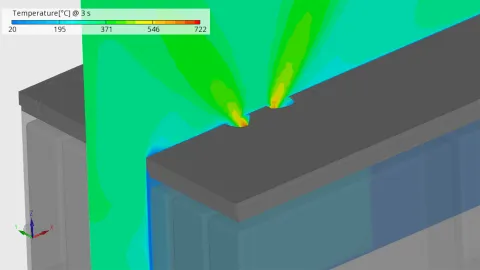
With the release of FIRE M 2025 R2, the simulation capabilities for PEM fuel cells have been significantly enhanced. One of the key advancements is the ability to model a fully realistic air startup scenario. To achieve this, several extensions have been integrated into the existing performance model, enabling a more accurate representation of the complex electrochemical processes involved.
Oxygen Reduction Reaction at the Anode: During air startup, the oxygen reduction reaction (ORR), typically confined to the cathode, also occurs at the anode. This behavior is a major contributor to the sharp rise in cathode potential observed during startup.
Enhanced Carbon Oxidation Mechanism at the Cathode: Under air startup conditions, the cathode potential can exceed 1.5 V, initiating corrosion of the carbon support structure. To model this phenomenon with greater fidelity, a second carbon oxidation mechanism has been introduced. This new mechanism is applicable for voltages above 1 V and incorporates six distinct oxide species and seven electrochemical reactions.
Platinum Oxidation at the Anode: At the onset of startup, the anode potential reaches approximately 1 V, significantly higher than during normal operation. As a result, platinum oxidation becomes relevant not only at the cathode but also at the anode, necessitating its inclusion in the model.
Electrochemical Double Layer Capacity: The dynamic voltage fluctuations during startup make it essential to account for the capacitive behavior of the electrochemical double layer. This aspect plays a crucial role in shaping the local voltage profiles at both the anode and cathode and is now explicitly considered in the simulation.
These enhancements mark a significant step forward in fuel cell simulation fidelity, supporting more robust design and analysis for real-world operating conditions.
Figure 1 shows typical air start-up scenario in a PEM Fuel Cell.

PEM Electrolyzer Degradation
With the release of FIRE M 2025 R2, a significant milestone has been reached: the introduction of the first degradation model for PEM electrolyzers. This model provides a detailed representation of key degradation mechanisms that affect the performance and longevity of these systems.
One of the primary degradation effects captured is chemical ionomer degradation. This process begins with oxygen crossover, which leads to the formation of hydrogen peroxide (H₂O₂). In the presence of metal ions, H₂O₂ reacts to produce highly reactive hydroxyl (OH) radicals. These radicals attack both the side and main chains of the ionomer, resulting in reduced ionic conductivity and thinning of the membrane and catalyst layers. Notably, this degradation is most pronounced in the cathode catalyst layer, as H₂O₂ formation predominantly occurs at voltages below 0.7 V.
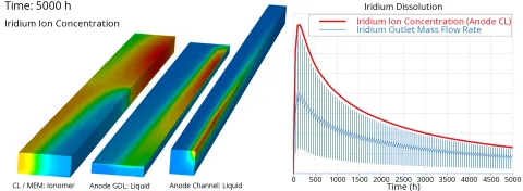
Another critical mechanism included in the model is iridium dissolution and redeposition at the anode. Under high potentials, iridium or its oxide can dissolve, similar to platinum. The dissolved iridium ions may migrate into the membrane and be carried away with the excess feed water. This not only leads to a loss of catalyst material but also contributes to Ostwald ripening, where iridium ions redeposit on larger particles, thereby reducing the electrochemically active surface area (ECSA).
The model also accounts for carbon and platinum degradation phenomena at the cathode, such as carbon oxidation, platinum oxidation, carbon corrosion, particle detachment, and agglomeration. While these effects are well-known in fuel cell cathodes, they are generally less pronounced in PEM electrolyzers due to the low local potential under standard operating conditions.
As with fuel cells, the degradation model in FIRE M is fully integrated with the performance model. This coupling allows for dynamic simulation of how degradation impacts key physical and electrochemical properties over time.
To support simulation times, the degradation models are compatible with the well-established subcycling method in the FIRE M fuel cell and electrolyzer module. This approach enables efficient computation over extended physical periods and numerous load cycles, maintaining reasonable calculation times.
Solid Oxide Fuel Cell Hot Box Simulation with Radiative Heat Transfer
FIRE M now offers the capability to simulate a complete Solid Oxide Fuel Cell (SOFC) hot box by integrating the SOFC stack model with an external reformer model using the heterogeneous chemistry module within a single domain. This enables a more realistic representation of catalytic fuel reforming and electrochemical conversion processes under high-temperature conditions. The unified modeling approach enhances the accuracy and fidelity of system-level simulations.
In many SOFC systems, operation takes place within thermally insulated enclosures. In such environments, surface-to-surface radiation between hot components and surrounding walls plays a significant role in heat transfer. To capture this behavior accurately, FIRE M fully supports application of the radiation module in all relevant domains. This enables detailed modeling of radiative heat exchange, contributing to improved thermal management and more precise prediction of temperature distributions throughout the system.
Battery
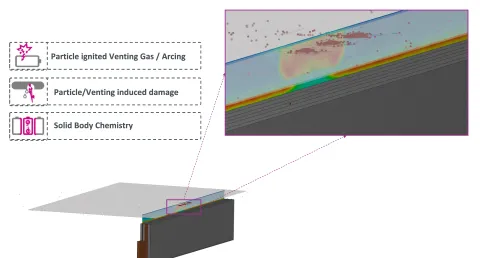
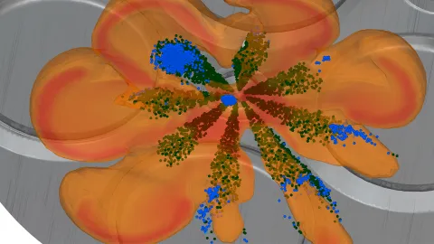
Battery Thermal Runaway – Coupled Kinetic/Venting/Particle Model
The kinetic modelling now bridges the gap between solid body heat release and the release of venting gas and particles, unifying the phenomena observed in a single battery cell during thermal runaway events. The amount of vent gas produced during thermal runaway is obtained from a reaction mechanism and the evaporation model.
Furthermore, particles can interact with their surroundings and provide information regarding heat transfer and kinetic energy transferred to solids during particle impact.
Battery Thermal Runaway Simulations on GPUs
In 2025 R1, embedded body simulations of single-phase flows without energy equation were supported on GPUs. FIRE M 2025 R2 supports running embedded body simulations of single-phase flows, without, but also with activated energy equation, and with embedded body interfaces (mass sources) on the GPU flow solver. Together with the already previously released capabilities for thermal multi-material domain simulations and species transport, battery thermal runaway simulations can now be fully performed on GPU nodes.
Improvements in Equivalent-Circuit Model
The equivalent-circuit battery model now allows to consider reversible heat (i.e. heat caused by entropy changes in the electrochemical reactions) through the newly introduced input “thermoelectric sensitivity”.
ICE-based Powertrains
IC-Engine Models With Incorporated Sprayblock
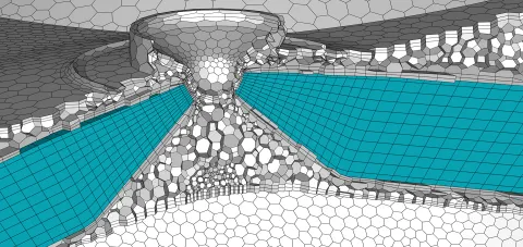
The use of sprayblocks in an otherwise arbitrarily oriented computational grid became popular over the years as they help reducing numerical diffusion in an efficient and effective manner and promote highly accurate calculation of fuel sprays and gas jets respectively.
When deploying FIRE M Engine with polymeshes, users leverage the tool’s embedding capability to incorporate existing meshes into the model. The main use case involves embedding structured blockmeshes for the spray region during the fuel injection phase. Up to now these blockmeshes were almost always created manually using the blockmesher being part of FIRE M.
With the 2025 R2 spray block definition gets significantly easier and faster. For this purpose two templates are provided, a single-block template and a two-block template. The templates can be fitted using a set of geometrical, alignment and discretization parameters. The sketch of the selected template adapts to parameter changes immediately. A "Create mesh" function allows to precisely check the position and size of the sprayblock relative to the actual engine geometry. In a single FIRE M Engine project multiple sprayblocks can be used and activated for a specified crankangle range.
Solving General Gas Phase Reaction Models Faster
Our experience shows that many chemical reaction mechanisms used to simulate combustion in internal combustion engines or for other purposes, are too large. This means they contain more species and more reactions than are necessary to solve the problem under investigation. This can lead to undesirably long, even excessive, computation times. Therefore, we now offer a way to reduce reaction mechanisms to the components essential for problem solving. The sdt_python module of FIRE M 2025 R2 provides commands that allow for a simple reduction of a reaction mechanism via a command line call and a control file. With such reduced mechanisms, we naturally achieve shorter simulation times – potentially even dramatically shorter simulation times.
ASAM OpenSCENARIO® XML Descriptions Directly in AVL Scenario Designer™
Native support of the ASAM OpenSCENARIO® standard combined with an intuitive usability is what our customers love about AVL Scenario Designer™. In this scope, we enriched the tooltip information of all user inputs to show field descriptions directly derived from the official standard documentation. This means, users don’t have to search in the standard documentation what a certain input field exactly means – they can just hover with the mouse over an input field to get more information directly from the ASAM standard.
Video 1: Input field tooltip descriptions directly from ASAM OpenSCENARIO® standard.
In Video 1 you can see this feature for the shape attribute of a speed change action. The definition of cubic, linear, sinusoidal and step are automatically shown in the tooltip based on the user choice. This feature underlines AVL’s commitment to the ASAM standards.
Introducing esmini as an Alternative Preview Playback Engine
Esmini is widely accepted in the OpenSCENARIO community because it offers a simple and reliable way to interpret and play back scenarios based on ASAM standards, without requiring complex infrastructure. Its consistent behavior and open-source transparency give users confidence that scenarios will run as expected across different environments. Integrating esmini into AVL Scenario Designer™ adds value by allowing users to design scenarios that behave identically when played back in standalone esmini, reducing the risk of misinterpretation and saving time during validation. This alignment between design and playback ensures a smoother workflow and more predictable results for scenario developers.
Video 2: Switching the playback engine in AVL Scenario Designer™
As you can see in Video 2, it is very easy for the user to switch the playback engine from our internal scenario interpreter to esmini and back. The user experience of the scenario design workflow is consistent across playback engines as it is only used in the backend to calculate the trajectory previews and event timeline information. The open architecture enables us to integrate output of other simulators to help users design scenarios for their target simulator – feel free to contact us if you want to learn more.
Virtual Passenger Comfort Rating With AVL DRIVE™
In automated driving, passenger comfort is a key differentiator. Whether it's a robo-taxi where people want to read emails and sip coffee, or a people mover at the airport where standing passengers expect smooth stops and starts, comfort shapes trust in the system.
This combined solution runs additional analysis on the results of scenario-based safety tests to also analyze the drivability and passenger comfort during the maneuvers. Allowing our customers to optimize the calibration of ADAS features and Autonomous Vehicles (AV) for a smooth ride experience without compromising on safety.

If you want to learn more about this solution, check out our free on-demand webinar.
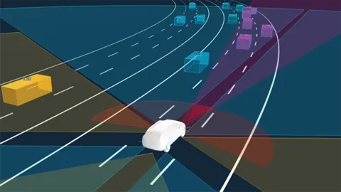
High-Level Sensor Fusion Using ASAM OSI® Sensors
AVL Scenario Simulator™ now supports high-level sensor fusion workflows, enabling users to validate perception systems using interpreted sensor outputs like detected objects instead of raw data. This approach simplifies development by allowing independent sensor processing, making it easier to reuse proven algorithms and accelerate debugging and prototyping. The simulator’s statistical sensor models run up to 1000x faster than real time and can be parametrized for effects like range or gaussian noise errors, helping users maximize test coverage and benchmark sensor configurations efficiently.
More information and a live demo can be found in the free on-demand webinar.
AVL VSM™ Unveils Turn-Key Driving Simulators, New Controls Configuration (DiL) and Joins Virtual Studio Dynamics (Testbeds)
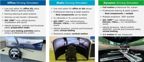
Turn-key Driving Simulators, from Static to Full Dynamic
Building, configuring and maintaining professional driving simulators can be a complex and time-consuming process. At AVL, we understand these challenges and offer turn-key solutions designed to eliminate the typical pain points our customers share. Our comprehensive toolchain ensures a seamless experience from start to finish, allowing you to focus on what truly matters: high efficiency and quality virtual development practices.
One of the key advantages of choosing AVL is our complete tool integration, encompassing both software and hardware components. This holistic approach ensures that all elements work precisely together, providing reliable and accurate simulation environments. Additionally, our solutions include correlated vehicle models, which significantly reduces risks and accelerates the implementation process of a new DiL system and related methods.
To further enhance efficiency, AVL provides expert training tailored to your specific needs and applications. The training helps your team quickly master the technology, speeding up the development cycles and maximizing the potential of your driving simulator, regardless of the system configuration or application focus. AVL turnkey driving simulators reduce development time and costs, while ensuring high precision and development efficiency.
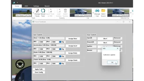
New Driving Simulator Controls Configuration
Our newly launched driver controls configuration and calibration feature enables users to tailor different aspects of the driving interface, including steering, pedals, gear controls, and ignition to meet specific testing or driver preferences. This level of adaptability is key for achieving realistic and repeatable results across a wide range of driving simulator types and use cases.
Built with versatility, the system supports a broad variety of hardware configurations, making it suitable for both office-based setups and professional Driver-in-the-Loop (DiL) environments. Whether you're running early-stage development testing or conducting high-fidelity validation, this flexible configuration ensures seamless integration and consistent performance.
The solution connects AVL VSM™ to a variety of commercially available steering and pedal systems, ensuring compatibility and scalability. The result is an enhanced user experience, delivering intuitive, precise, and reliable driver control that mirrors real-world vehicle behavior, helping engineers extract meaningful data and optimize performance faster.
AVL VSM™ Joins Virtual Studio Dynamics 2025
VSM is now fully integrated with the Virtual Studio Dynamics platform, enabling seamless interaction between simulation and multiple physical testbeds. This powerful integration bridges the gap between virtual and real-world testing, allowing engineers to develop, validate, and refine vehicle functions, systems and components in a streamlined, efficient workflow.
With this offering, users can test critical vehicle attributes, such as energy management, vehicle dynamics, driveability, and safety across multiple environments, including tarmac, low-friction surfaces, off-road conditions, and racetracks. The system also enables the rapid generation of virtual twins within just two days using AI-based modeling, significantly accelerating the development timeline.
Customers benefit from ready-to-use vehicles and testing templates, a 40% reduction in preparation time, and a high correlation quality of over 90%. A single model can be used across various environments, ensuring flexibility, consistency, and scalability throughout the development process. Simulation and testing are now more efficient, accurate, and adaptable than ever before.
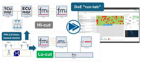
The latest release of our co-simulation and integration platform, designed to streamline and enhance collaborative development and testing in Software-in-the-Loop (SiL) environments, introduces advanced features that empower teams to seamlessly integrate, validate, and optimize their SiL workflows for greater efficiency and innovation.
The most exciting new features include:
- Collaboration Server – for distributed IP-protected co-simulation.
- FMI 3.0 Layered Standard virtual bus - for faster vECU integration.
- AVL EXCITE™ M interface component - for seamless 1D-3D coupling
- SiL-related efficiency add-ons:
- Run-Tab for KPI-based DoE monitoring
- FMI 3.0 time-based clocks for event-triggered testing
- Automated model connections: implicit name-based
- Large MF4 file support.
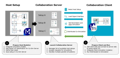
Collaboration Server
FMUs are widely used for model sharing in simulations, but they pose risks of exposing sensitive intellectual property since model details may be accessible in resources or binaries. Model.CONNECT™ Collaboration Server solves this by providing proxy client FMUs that connect to server-hosted models, ensuring IP protection while enabling seamless co-simulation. The server can be hosted by OEMs or suppliers, supports secure HTTPS connections, and allows flexible access control, including revoking usage rights. Beyond IP protection, it also enables collaboration when models are too complex to package or involve physical components, with real-time interaction possible under suitable time-step sizes.
FMI 3.0 Layered Standard Virtual Bus (FMI-LS-BUS)
Modern vehicles integrate 100+ ECUs (e.g., ECM, BMS, comfort systems), interconnected via CAN, LIN, FlexRay, or Ethernet. To validate these complex networks early, OEMs increasingly rely on virtual ECUs (vECUs) in simulation. For this, the FMI Layered Standard for Network Communication (FMI-LS-BUS) extends FMI 3.0 to enable standardized network-level interaction between FMUs. Model.CONNECT already supports vECUs following the v1.0.0-rc1 draft.
Two abstraction levels are defined:
- High Cut (Physical Abstraction Layer):
Signal/frame-based communication using FMI 3.0 terminals. Signals, frames, and timing (via clocks) are managed automatically in Model.CONNECT through a Virtual Bus component. This allows multiple vECUs to connect efficiently using .dbc or arxml descriptions. Missing writers for signals are flagged and can be supplied by constants, tables, or measurement replays. - Low Cut (Network Abstraction Layer):
Bit-level communication including protocol effects such as CAN arbitration or bus errors. Data is exchanged through binary Tx/Rx variables and synchronized with clocks. Operations like Transmit, Confirm, or Arbitration Error enable detailed bus behavior simulation. This supports analysis of bus load, delays, error handling, or priority conflicts.
FMI-LS-BUS enables scalable and interoperable network simulation of vECUs. Model.CONNECT integrates both abstraction layers and is among the first tools to implement this emerging standard, as recently presented at ASAM. Besides that, Model.CONNECT also supports FMI 3.0 time-based clocks for event-triggered SiL testing.
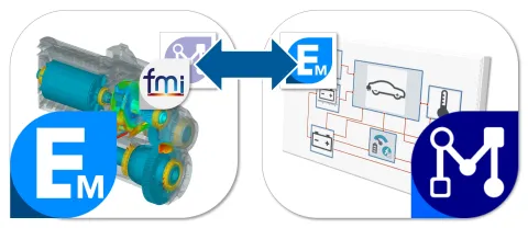
New AVL EXCITE™ M Interface Component
The new release of Model.CONNECT now also supports EXCITE M with a dedicated model interface. This means that the EXCITE M model will be simulated within the same process (using FMI technology in the background).
The configuration is very simple. An EXCITE M model within the same project file can be directly selected and all its ports become automatically available.
Release 2022 R2
- Virtual System Development - Concept, Layout and Integration
- Virtual Function Development - Automated and Connected Mobility
- Virtual Battery Development - From Cell to Vehicle
- Virtual Fuel Cell Development - Components and Systems
- Virtual Driveline Development - Transmission and E-Drive
- Virtual ICE Development - Durability and NVH
- Virtual ICE Development - Performance and Emissions
Stay tuned
Don't miss the Simulation blog series. Sign up today and stay informed!
Stay tuned for the Simulation Blog
Subscribe and don‘t miss new posts.