Suppression of the Gyroscopic Effect in Motor Rotor Dynamics by Viscous Oil Film
Published on June 30, 2026 · 8 min read
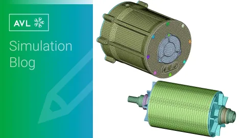
The structural design of the rotor directly affects the distribution of moments of inertia and stiffness. Meanwhile, unavoidable mass imbalances during manufacturing (such as permanent magnet assembly deviations or lamination stack errors) generate centrifugal excitation forces during high-speed rotation, leading to forced vibration of the rotor. In severe cases, this can cause resonance instability. Electric drive motors operate over a wide speed range (typically covering low-speed torque zones to high-speed power zones), requiring unbalanced response analysis across the entire speed range.
From a mechanical analysis perspective, the presence of unbalanced mass, in a high-speed rotor, results in unbalanced centrifugal forces. This causes radial motion of the rotor, generating Coriolis forces perpendicular to the direction of motion. The rotational torque produced by these forces is known as gyroscopic torque, which splits the radial vibration modes of the rotor into forward and backward whirling modes. If external excitation frequencies couple with these modes, the gyroscopic effect is further amplified, leading to significant radial deformation of the rotor shaft.
When rotor centrifugal forces are balanced (no additional Coriolis force), the rotor dynamic equation is:
[M]{ẍ} + [C]{ẋ} + [K]{x} = {f}
Characteristic equation: ([M]ω² + [K]){x} = 0
When rotor centrifugal forces are unbalanced (additional Coriolis force producing torque), the rotor dynamic equation is:
[M]{ẍ} + [C]{ẋ} + [G]{ẋ} + [K]{x} = {f}
Characteristic equation: ([M]ω² + [G]ω + [K]){x} = 0
Here, [G]{ẋ} is the gyroscopic term. Since [G] is a skew-symmetric matrix and depends on rotor speed, it causes splitting of structural modes, resulting in forward and backward whirling modes.
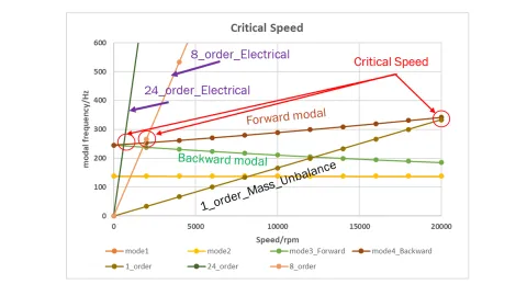
For high-speed motors, due to the high rotational speed, the critical speed map is shown below. The 3rd and 4th modes of the rotor split into forward and backward whirling modes:
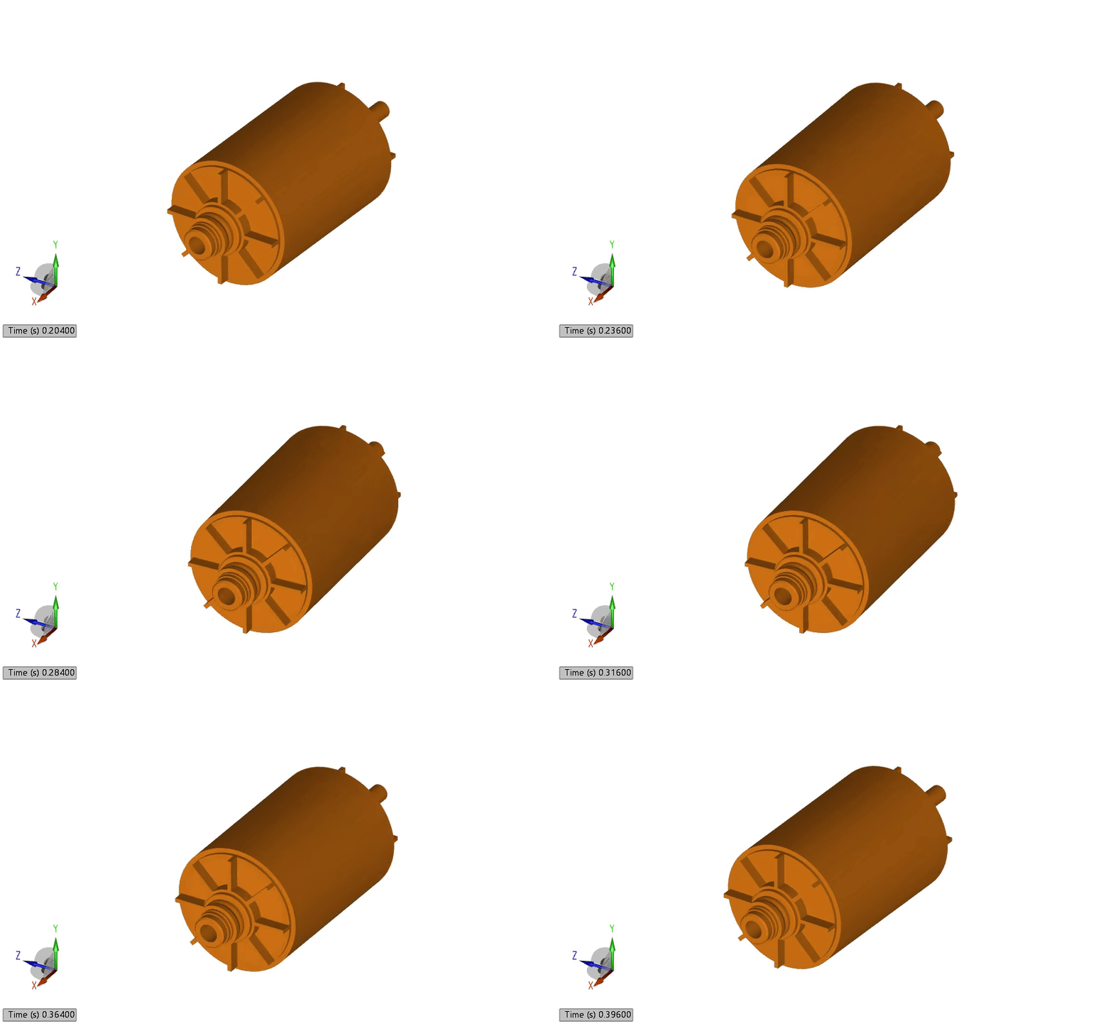
The longitudinal bending mode shape of the motor rotor at 0 rpm is shown below:
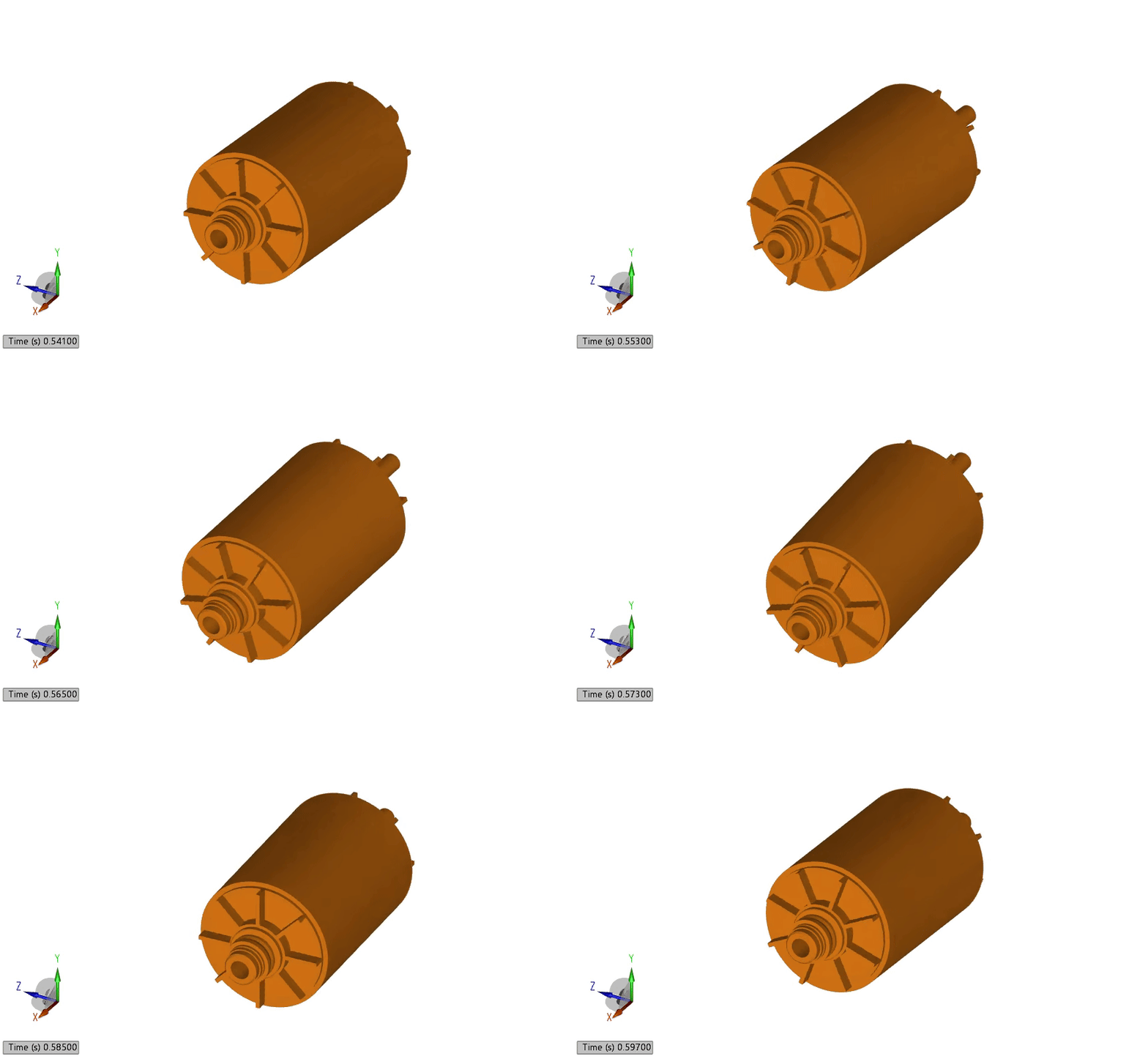
The gyroscopic mode shape of the motor rotor at 10,000 rpm is shown below:
When the forward or backward whirling modes of the rotor coincide with the rotational speed, resonance instability occurs, the gyroscopic effect intensifies, rotor misalignment increases, and the reliability of the support bearings faces severe challenges. To mitigate the gyroscopic effect at high speeds, viscous lubricating oil can be applied to the outer ring of the roller bearings to reduce radial vibration and weaken the gyroscopic effect. The following section uses AVL EXCITE™ M for virtual evaluation of such concept.
To validate the influence of viscous oil film on motor rotor dynamics, a comparative study was conducted using a floating outer ring configuration for the motor roller bearings. Oil holes were machined into the bearing housing to supply lubricating oil, establishing an oil film between the bearing outer ring and the housing. A motor rotor dynamic model was built using EXCITE M for simulation validation.
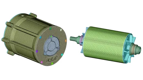
The rotor and stator were reduced using finite element methods to introduce stiffness and mass matrices, allowing accurate simulation of structural flexibility and inertial characteristics in subsequent dynamic calculations.
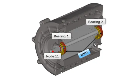
Deep groove ball bearings were used for the connections between the motor rotor and stator. The roller bearing joint in EXCITE M accurately simulates the dynamic characteristics of these bearings. The joint uses Hertzian contact algorithms to precisely calculate contact forces between the raceways and rolling elements. Additionally, this joint supports the inclusion of key influencing factors such as nonlinear stiffness, damping characteristics, friction effects, assembly clearances, and preload, enabling comprehensive and accurate simulation of bearing dynamic behavior.
The oil film between the bearing outer ring and the housing was simulated using the EHD2 joint. The EHD2 joint employs a coupled solution of structural dynamics equations and the Reynolds equation, accounting for the effects of pressure and clearance on the oil film. Furthermore, the EHD2 joint incorporates a temperature field model, allowing calculation of the effect of frictional heat generation on oil viscosity throughout the mechanical operating cycle.

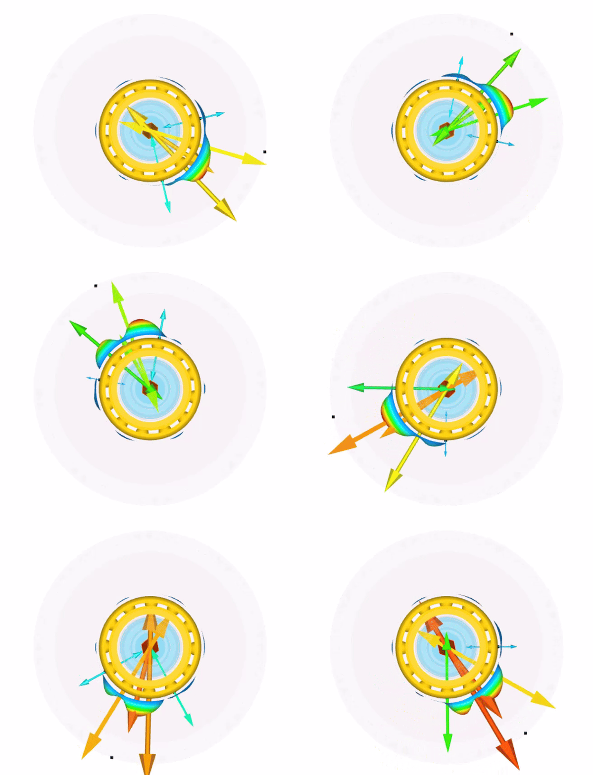
Due to mass eccentricity, the motor rotor generates dynamic radial displacement during operation, which alters the electromagnetic field distribution and produces dynamic radial magnetic pull. This magnetic pull further influences the radial displacement of the rotor. To accurately capture this characteristic, AVL E-Motor Tool was used to obtain electromagnetic forces at different eccentric positions of the motor, and the EMC2 motor joint in EXCITE M was employed to establish an electromechanical coupling model of the dynamic eccentricity of the motor rotor.
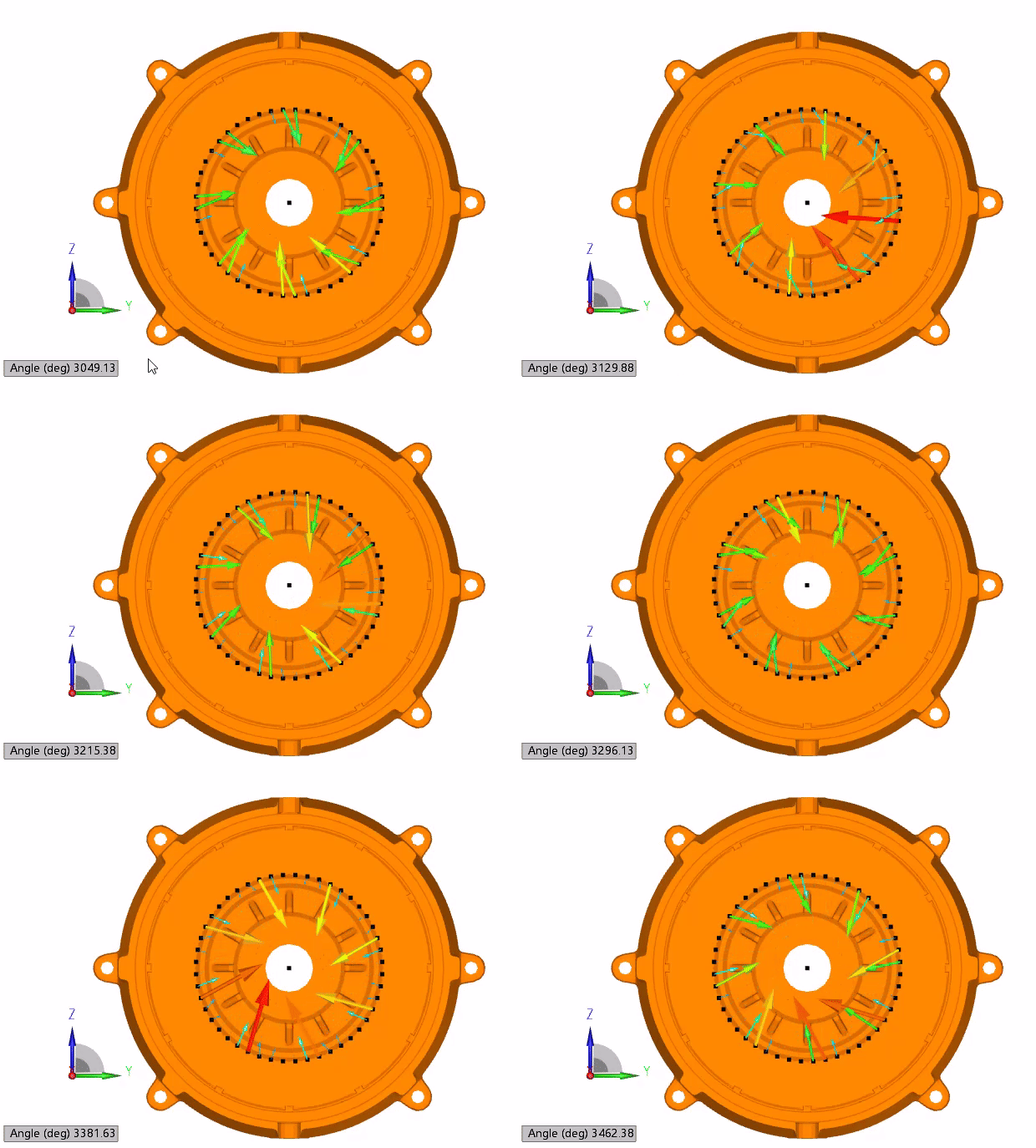
Due to manufacturing tolerances, the motor rotor has some mass eccentricity. Combined with bearing clearances, the air gap in the motor's electromagnetic field varies dynamically, resulting in unbalanced radial electromagnetic forces and a dynamic radial magnetic pull on the rotor.
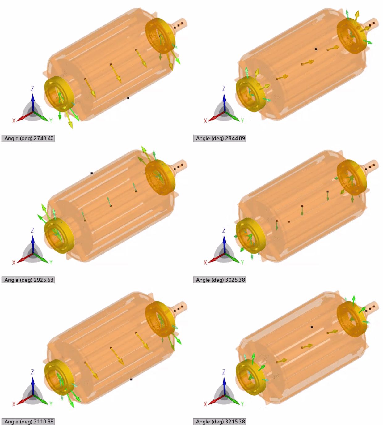
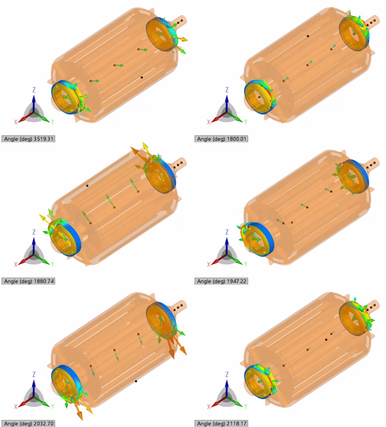
Under the action of radial magnetic pull, the load on the bearings at the motor rotor ends increases. The magnetic pull further amplifies the radial bending deformation of the rotor, increasing the displacement at the rotor ends.
Pressure distribution and oil fill results for the floating bearing outer ring and housing:

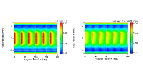
For the floating bearing support structure, the presence of the oil film in the floating clearance provides damping that attenuates the radial motion of the rotor. This effectively reduces the load and displacement at the rotor ends, helping to improve the gyroscopic effect of the rotor.


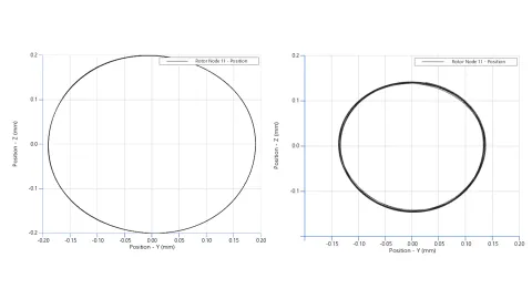
Rotor unbalance will generate dynamic centrifugal forces on the rotor structure and bearings. In addition, rotor eccentricity causes the rotor to experience unbalanced radial magnetic pull. Unbalance forces and magnetic pull result in radial displacement at the rotor ends and a gyroscopic motion behavior. This not only affects the axial alignment of the rotor and housing at the rotor ends but also imposes significant radial support loads on the rotor support bearings, posing a challenge to roller bearing reliability.
For floating bearings, the damping provided by the oil film in the floating clearance reduces the radial motion of the rotor, reduces radial displacement at the rotor ends, improves axial alignment of the rotor and housing, lowers bearing loads, and enhances bearing reliability.
Stay tuned
Don't miss the Simulation blog series. Sign up today and stay informed!
Read More About This Topic
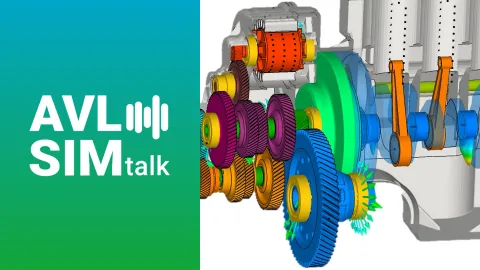
This SIMtalk provides a concise overview of the complete AVL EXCITE™ M workflow, highlighting the key steps that most strongly impact simulation efficiency and accuracy. It focuses on practical tips and proven techniques to reduce setup time, avoid common errors, and improve overall productivity and result quality.

In this release overview, we share the latest features and updates included in AVL Simulation Suite 2026 R1.
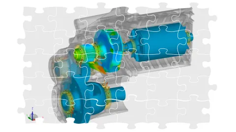
This guide shows how to approach debugging in AVL EXCITE™ M systematically to understand and improve model behavior.
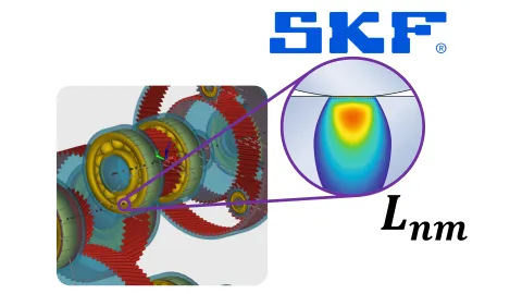
Use the SKF online calculation service directly within AVL EXCITE™ M to evaluate rolling bearing lifetime accurately and seamlessly in your simulation workflow—based on ISO 281, SKF Rating Life, and the SKF Generalized Bearing Life Model.
Stay tuned for the Simulation Blog
Don't miss the Simulation blog series. Sign up today and stay informed!