Wind Turbine System Dynamics Simulation With AVL EXCITE™ M
Published on April 22, 2026 · 9 min read

The multibody dynamics simulation software AVL EXCITE™ M can consider gear flexibility and deformation, macro and micro geometry gear parameters, and elasto-hydrodynamic lubrication contacts in plain bearings. It is used for wind turbine drivetrain gear meshing analysis, plain bearing lubrication analysis, overall wind turbine NVH and reliability analysis. Numerous wind turbine manufacturers have also integrated this analysis task into their product development and design.

The EXCITE M complete wind turbine assembly model can consider in detail the mutual influences of various wind turbine subsystems and perform accurate multi-body dynamics calculations based on its real load boundaries. The model detail level can be adjusted depending on the development stage and the specific focus of the simulation. The modeling features of the EXCITE M wind turbine model are as follows:
Flexible Bodies
All structural bodies can use 3D full flexible body, typically FE based reduction models. This approach accounts for the impact of the component’s dynamic deformation on gear meshing, bearing forces, etc.

Gear Contact
Accurately considers gear meshing effects: Considers the impact of gear macro geometry and micro modification parameters on gear meshing.

Figure 3: Gear Microgeometry
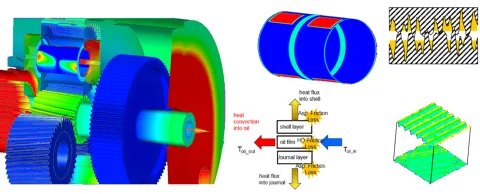
Hydrodynamic Bearings
The detailed plain bearing lubrication model combines advanced elasto-hydrodynamic (EHD) lubrication theory including asperity contacts, with the motion and deformation results of each contacting component. It systematically couples structural stiffness, lubricant properties and supply boundaries, lubrication and heat transfer boundary conditions, and the surface microgeometry.
The model accurately calculates the hydrodynamic contact results on the plain bearing surface, evaluates bearing lubrication conditions, friction, wear and diagnoses common faults.
Extended Reynolds Equation:
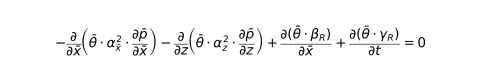
Equation of Motion:

Electro-Mechanical Interaction
Detailed electric generator/motor models are established based on electromagnetic field analysis, enabling generator control at different speeds and torque levels. Additionally, electromagnetic excitation from the generator can be considered as an NVH excitation source.

Dynamic Loads
Based on real load boundary conditions, the dynamics model can be driven by loads derived from tests or simulations. Loads can be applied under steady‑state or transient operating conditions.
Plain Bearing Lubrication Analysis
As mentioned above, EXCITE M software, based on hydrodynamic lubrication theory, can simulate plain bearing lubrication accordingly. On one hand, the model accounts for bearing surface micro-roughness; on the other hand, it considers the influence of surface roughness and different oil supply boundary conditions.
As shown in Figure 6, the model defines an axial barrel shape for the planet gear pin, which can reduce bearing edge load to some extent. Different oil supply boundary conditions can also be defined, as illustrated in Figure 7.
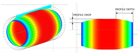
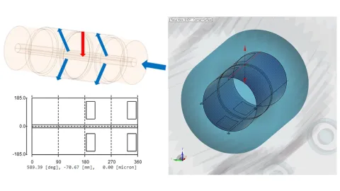
Figure 8 shows the EHD analysis results for a three-planet bearing. From the total contact pressure and asperity contact pressure distributions, it is clearly evident that the bearing exhibits significant misalignment on both sides. Localized thermal load concentrations occurs at the edges, which may lead to local overheating and surface damage.

Based on the EHD contact pressure distribution results, in combination with the built-in Archard wear model, the wear distribution on the bearing surface can also be calculated. As shown in Figure 9, severe misalignment at the bearing edges, results in pronounced edge wear. After optimizing the shaft profile, both asperity contact pressure and wear are significantly reduced.

The total bearing surface contact pressure can also serve as a boundary condition for finite element analysis. By mapping the bearing pressure loads onto the planet pin, slip at the interference-fit contact surfaces can be analyzed, allowing assessment of planet carrier loosening, planet pin loosening, and deformation of the non-linear planet carrier structure.

Gear Meshing Analysis
By defining detailed gear macro and micro geometry modification data, combining dynamics calculation results, and considering the influence of shaft, gear, and housing flexibility deformation, the gear surface meshing conditions can be accurately analyzed.
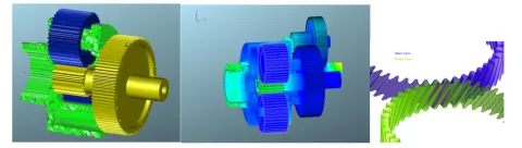
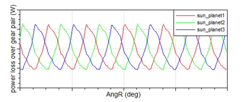
Figure 12 shows the tooth flank contact pressure distribution during gear meshing. Combined with the contact pressure distribution map and the tooth flank load distribution coefficient calculated by the software, this can guide subsequent tooth flank modification design. By integrating the system model, gear system power loss and transmission error can be accurately calculated.


System Torsional Vibration Analysis
By integrating the complete wind turbine assembly model and considering the wind loading during turbine operation, changes in rotational speed and load for each component during rotor acceleration can be calculated. Instantaneous impacts on system components during transient events are also considered. Figure 15 shows the speed and torque variations during rotor acceleration and emergency stop events.

For unsteady-state conditions, such as extreme gusts or wind lulls, integrating the system's bending-torsion coupling effects and generator unit control allows calculation of the speed and torque variations of each component to assess system reliability.
NVH Analysis
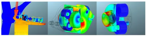
Based on the complete wind turbine dynamics model, the forces on each connection pair can be calculated. Then, combined with the reduced substructure recovery matrix, the vibration and noise of the entire structure can be obtained. Figure 16 shows the housing surface vibration velocity surface plot, providing an obvious view of the vibration levels at different positions on the housing surface.

Reliability Analysis
Combined with the dynamics analysis results, the forces over time on various components can be calculated. Using these results as boundary conditions for the modal stress recovery calculation, transient stress distributions in wind turbine components can be efficiently determined.
Based on the EXCITE M software platform, a complete and detailed wind turbine system dynamics model can be established. This enables accurate simulation of plain bearing lubrication, friction, and wear, as well as gear meshing behavior, drivetrain torsional vibrations, NVH characteristics, and overall system reliability.
Stay tuned
Don't miss the Simulation blog series. Sign up today and stay informed!
Read More About This Topic
Achieving carbon neutrality requires a fundamental transformation in how energy is produced, stored, and used. Green hydrogen – produced via renewable-powered electrolysis – is emerging as a key enabler of this transition.

How 3D simulation in SOEC systems enables green hydrogen and syngas production.

How simulation reveals the physics of mobile hydrogen refueling and helps optimize efficiency, safety, and speed.

As the demand for clean hydrogen grows, PEM electrolysers are gaining traction in global markets. This blog explores how multiphysics system simulation is accelerating their development and helping engineers meet performance, efficiency, and durability targets.
Stay tuned for the Simulation Blog
Don't miss the Simulation blog series. Sign up today and stay informed!