
Accelerate PEM Fuel Cell Development with Model-Based Simulation
Published on January 26, 2026 · 3 min read
Realizing virtual fuel cell development requires a simulation platform capable of representing the entire system — from the physics of the membrane to vehicle-level integration. AVL CRUISE™ M provides exactly that.
It delivers a unified, multi-physics environment where electrical, thermal, liquid and gas domains are modeled consistently within one framework. With its dedicated library of PEM fuel cell components — stacks, humidifiers, compressors, valves and heat exchangers it helps us to construct system models that accurately mirror real hardware.
The platform supports both Low Temperature (LT) and High Temperature (HT) PEM technologies, allowing users to evaluate different concepts within the same environment. The focus of this article will be on LT-PEM system modelling, CRUISE M provides full capabilities for HT-PEM modelling as well, which we covered in a separate blog post: High Temperature PEM Fuel Cell Model in AVL CRUISE™ M.
Built-in parameterization tools such as the PEMFC System Generator or the PEMFC Stack Wizard streamline data matching, while open interfaces enable seamless integration with control systems and software. From a single stack to a complete vehicle, CRUISE M empowers engineers to model, analyze and optimize fuel cell performance with precision – accelerating innovation toward cleaner, more efficient mobility.
CRUISE M can be applied across the full range of fuel cell development tasks. At the smallest scale, it allows detailed analysis of cell and stack behavior, including electrochemistry, humidification and degradation modelling. The same model can be then extended to the system-level studies where the balance of plant components and their control logic interact with the stack. This allows us to assess how system operation influences degradation of the stack over time.
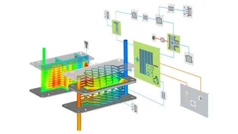
The workflow scales up also to complete vehicle integration. This includes passenger cars, heavy-duty trucks, trains, maritime and even aerospace applications (Figure 1). An approach like this ensures a consistent evaluation across all development stages from the first cell model to full powertrain operation.
In addition to simulation, the models can be used directly in the Model-in-the-Loop, Software-in-the-Loop and Hardware-in-the-Loop environments, as well as Virtual Testbed setups. This allows the same physics-based model to support the controller development, calibration and system validation long before the hardware is available, maintaining the consistency all the way into testing. The topic was described in more detail at our SIMpulse event - From Challenges to Solutions: Leading PEM Fuel Cell Innovation Through Simulation.

Developing a LT-PEM fuel cell system isn’t just about modeling the stack — it’s about understanding how the entire system behaves under real operating conditions. The stack’s performance depends heavily on how well the surrounding Balance of Plant (BoP) components work together: the air and hydrogen supply, humidification, cooling, water management and control systems. Capturing these interactions across different levels of complexity — from component to system to vehicle — reflects the logic of the V-diagram, where simulation supports every stage from concept design to validation.
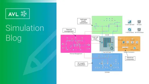
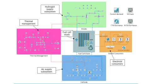
As shown in Figure 2, the complete LT-PEM fuel cell system model includes all key subsystems which are hydrogen and air supply, thermal management and the fuel cell stack, integrated into a single simulation environment.
In the next section we will break down and describe each of the subsystems.
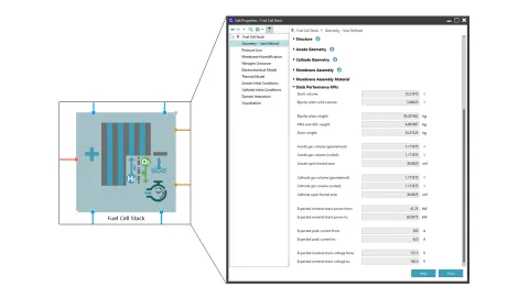
The LT-PEM fuel cell stack is the heart of our system. It delivers power based on the amount of hydrogen and oxygen supplied, transforming these reactants into electricity, water and heat. The component is represented in Figure 3, showing how the LT-PEM Fuel Cell stack integrates electrochemical, gas flow, thermal and electrical domains.
The PEM Fuel Cell Stack component in the CRUISE M library comes with default data, but it can be adjusted according to match the stack of interest. Based on the input data, the model calculates Stack Performance KPIs, providing a rough guide to verify that the dimensions are within a reasonable range and helping to prevent implausible or inconsistent model inputs.
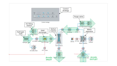
Hydrogen is the lifeblood of a LT-PEM fuel cell and delivering it at exactly the right flow, temperature and pressure is essential to keep the stack running efficiently and safely. That’s the job of the anode media supply subsystem. The subsystem layout with marked flow direction is illustrated in Figure 4.
Air Supply Subsystem – Managing Oxygen Flow
In a LT-PEM fuel cell, the cathode needs a precise supply of oxygen to operate efficiently. The cathode media supply subsystem ensures the stack receives air at the correct mass flow, pressure, temperature and humidity, keeping the system stable and reliable under all conditions. The subsystem with the air path flow direction and its main components is shown in Figure 5.
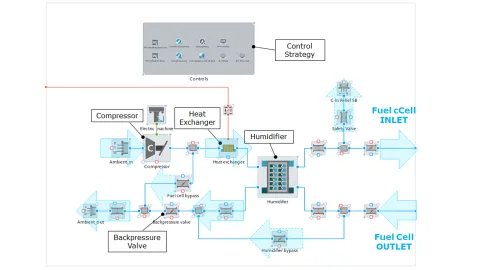
In a LT-PEM fuel cell system, maintaining the right temperature is critical. If the stack is too cold, it can’t reach full performance and if it’s too hot, components may degrade prematurely. That’s why an effective thermal management system is essential for reliable and efficient operation. The thermal management topology, with marked parallel branches and coolant flow direction is shown in Figure 6.

Setting up the model is just the beginning — it’s what enables us to use it for its true purpose. Thanks to the multi-disciplinary nature of the model, we can simulate a wide range of real-world use cases and operating scenarios.
With this foundation in place, let’s explore a few representative use cases that highlight how simulation supports design decisions and accelerates fuel cell system development.
Modeling Stack Degradation and Lifetime Prediction
Stack degradation is one of the greatest concerns of stack manufacturers. The stack represents a major part of the system cost and once degradation sets in, the stack is difficult to repair without full replacement.
The stack itself is a component that is very sensitive for the operating condition. Here we’re talking about the pressure levels (both absolute pressure and the difference between the anode and cathode sides), humidity (enough to humidify the membrane and not too much to cause the flooding), temperature (again high enough to increase the reaction rate but not too high) and much more. These quantities act as stressors for the stack and strongly influence its long-term behavior.
Incorrect steering of these conditions leads to the chemical and mechanical degradation of the stack, where the combination of both lead to increased internal resistance, reduced voltage or ultimately the system failure. Because the degradation rate directly affects lifetime targets and warranty margins, it becomes one of key KPIs across almost all development use cases.
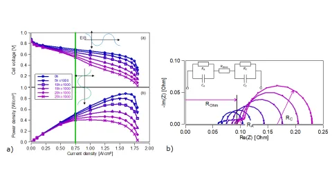
In CRUISE M we coupled the fuel cell system model with the mechanical and chemical degradation models, to capture long-term stack behavior. For the demonstration purposes we ran the 25000 h long accelerated stress test, accelerated by a factor of 1000. We observed the significant decrease of cell voltage and stack power density, which gradually decline over time. This can be seen in Figure 7 where the blue color represents the fresh stack and pink color represents a degraded stack. Furthermore, on the impedance spectroscopy (EIS) diagram the increase of internal resistances can be observed (blue-fresh stack, pink – degraded stack).
This insight allows us to evaluate operating strategies, compare design concepts and optimize the balance of plant in order to minimize the degradation rates and achieve the longest possible lifetime without relying only on time-consuming durability testing.
We dived deeper into this topic in our SIMpulse event: Next Chapter in PEM Fuel Cell Development: From DIY to Smart Simulation.
Compressor Matching for Optimal Air Supply
Designing the air supply system for a LT-PEM fuel cell is all about ensuring the stack breathes exactly as it should. The compressor is one of the most important components, which must deliver the right amount of air at the right pressure to keep the system efficient, responsive and reliable under all load conditions.
The selection of the compressor starts with the fuel cell stack requirements — its power demand dictates how much oxygen is needed and at what pressure. From there, we can derive the air mass flow based on stoichiometry, current and gas properties, while the required pressure ratio depends on the pressure losses across the other components on the cathode side, such as the heat exchanger and humidifier.
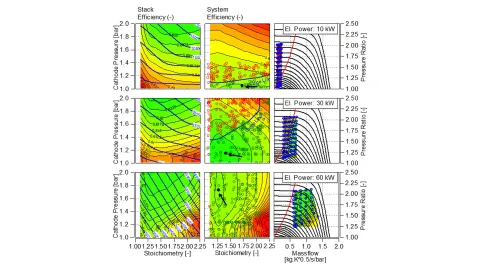
By simulating these interactions across various operating points, we can visualize how mass flow and pressure ratio evolve with stack current, gaining valuable insight into system dynamics. This understanding forms the basis for choosing an optimal compressor — one that achieves performance targets without being oversized or inefficient. This process can be seen in Figure 8, where the contour plots illustrate how stack and system efficiency vary with cathode pressure and stoichiometry for different electrical power levels. The plots at the right side show the corresponding air mass flow and pressure ratio maps, highlighting how compressor operation interacts with stack performance.
With CRUISE M, this entire process is integrated within a single, consistent model environment, allowing precise system sizing, compressor matching and performance assessment early in the development cycle.
Cold and Freeze Start in LT-PEM Fuel Cells
For LT-PEM fuel cells, starting in cold conditions presents a unique challenge. At low temperatures, water produced in the electrochemical reaction can freeze inside the membrane, gas diffusion layers or gas flow channels. This blocks reactant access and potentially also damages the stack. The cold start procedure is therefore critical for applications such as automotive, where reliability and immediate power delivery are expected in all weather conditions.
There are many strategies on how to start the fuel cell system in the freezing conditions – ranging from the variation of the start current, applying external heating, dry purging the system during the shutdown and much more. Here we will briefly touch one of the cases – the variation of current density.
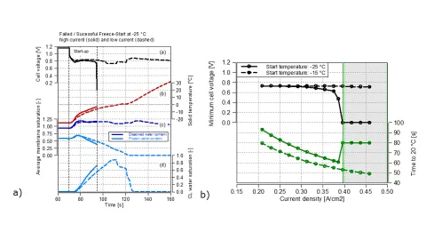
At a first glance the increase of current during a cold and freeze start seems smart – more current means more heat and therefore faster heat up, but in a LT-PEM fuel cell that logic can backfire. In a study we observed, that at -25 °C of ambient temperature, the stack at higher current density (~0.42 A/cm2) which is represented by the by the solid line on a Figure 9 performs worse that the stack at lower current density (~0.29A/cm2), represented by a dashed line. This happens because the stack operating at high current density not only heats up faster but also produces the water faster. That water then freezes inside the catalyst layer which results in blocking the gas flow and causing the start to fail at approximately 95 seconds.
Furthermore, the study on a startups at a different current densities was performed (Figure 9) and we observed that in the higher ambient temperature (-15°C) the startup current density does not play a large role for our stack, but as we go lower (-25°C) the careful selection of startup current density plays a difference between a failed and successful start-up.
If you’re interested in more details, watch our webinar Optimizing Your PEM Fuel Cell Cold Start Strategy.
Optimizing the Purge Valve Strategy for Efficiency and Longevity
Purge valve strategy is a critical aspect of LT-PEM fuel cell operation and balance-of-plant design. To maximize efficiency, unused hydrogen exiting the stack is recirculated back into the system. Along with hydrogen, other species – primarily nitrogen and water – are also recirculated. Water is removed via a water separator, but nitrogen can accumulate over time, leading to local hydrogen depletion, voltage drops and overall performance loss.
This hydrogen starvation accelerates carbon corrosion, permanently damaging the catalyst layer and reducing stack lifetime. To prevent this, a purge valve is installed at the stack outlet to remove nitrogen from the recirculation loop. However, purging nitrogen inevitably also wastes some hydrogen. The challenge lies in optimizing the purge strategy which aims on removing nitrogen efficiently while minimizing hydrogen loss, ensuring both reliable performance and extended stack durability.
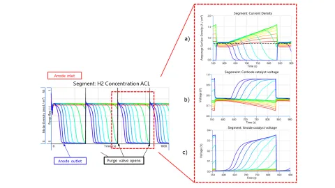
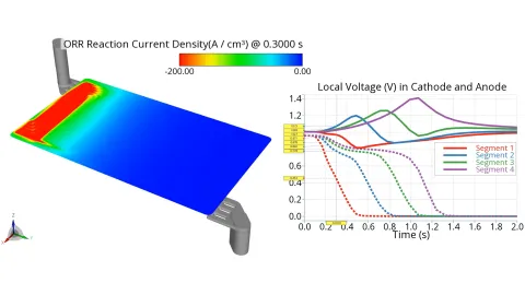
We did a study where the valve is closed during large parts of operation. Due to the consumed hydrogen and on the other hand the nitrogen and water crossover it comes to local reactant starvation towards the anode outlet, which results in local current density drop which can be observed in Figure 10.a. This stimulates the upstream segments which temporarily take over the current production in order to reach target current density (black dotted line). The cathode catalyst potential consequently rises towards the OCV (Figure 10.b) and the anode catalyst potential shifts to maintain the cell potential difference, resulting in a voltage increase on the anode side (Figure 10.c). The purge activation then clears the nitrogen from the loop and restores the hydrogen concentration, ensuring normal reaction conditions.
Designing LT-PEM fuel cell systems is always a balancing act — efficiency, durability and cost, all depend on how well every subsystem works together. CRUISE M simplifies this challenge by bringing electrochemical, thermal and control interactions into one simulation environment. It enables users to virtually test and optimize performance, from cold starts to compressor sizing and degradation studies, cutting development time and boosting their confidence before building a single prototype.
Stay tuned
Don't miss the Simulation blog series. Sign up today and stay informed!
Read More About This Topic
Fuel cells and electrolyzers are excellent solutions for efficiently achieving a CO2-neutral future. Especially since their application is multifaceted. It ranges from vehicles of all sizes to energy generation and storage to the starting point for synthetic fuels (e-fuels). Develop and optimize targeted fuel cell systems by using our simulation.

As PEM fuel cells move to the forefront of heavy-duty transportation and aviation, development teams are under growing pressure to deliver systems that meet ambitious performance, durability, and efficiency targets.

SIMpulse stands for innovative insight into the ever-evolving landscape of simulation technology. Experience a dynamic showcase spotlighting the diverse facets of simulation applications, from automotive design to energy optimization and beyond.
How a system handles fuel cell air start-up can make or break efficiency and lifetime. This article explores the underlying physics and the tools that ensure a stable, reliable start every time.
Stay tuned for the Simulation Blog
Don't miss the Simulation blog series. Sign up today and stay informed!