
Leveraging Simulation to Achieve Highly Efficient Vehicle Thermal Management
Published on April 24, 2024 · 11 min read
Driving range is one of the key sales drivers of battery electric vehicles and to the end customers, every kilometer counts. There are several ways the total efficiency of the vehicle can be increased, such as improving aerodynamics or decreasing vehicle weight, but one of the major contributors is an efficient thermal management system (VTMS). Because of the many power consumers that are part of the VTMS, it offers a lot of energy saving potential. It also has an element of safety and durability by keeping powertrain components at optimal temperatures. A typical thermal management system in a modern-day battery electric vehicle is rather complex. Most vehicles have a battery coolant circuit, that can also be used to control the temperature of the oil used to cool the electric motor and a dedicated heating circuit for the cabin and battery is also very common. A refrigerant system is required to, on one hand, cater to the comfort requirements of the passengers, and on the other hand, the comfort requirements of the battery. As the required temperature level of the battery is very moderate, it’s not always possible to rely on the ambient as a heat sink. This means that the refrigerant circuit has to be used to cool down the battery. In the winter time, there is also not enough waste heat that could be used to ensure sufficient heating of the cabin and battery, meaning the refrigerant circuit can operate as a heat pump, or an electric heater can be used. All of the chipsets and processing units on board (e.g. ADAS, DCU) also require cooling. An example of a modern day vehicle thermal management system is presented in the below figure. System models can be a demanding task, calling for expertise in the required stack configuration, the media supply components, their sizes, arrangement, and controls to run transient simulations.
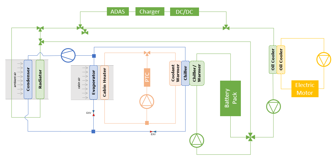
Having this many systems on board also means that there are many components to consider. Each of these systems has a pump or compressor, there are multiple heat exchangers connecting the circuits and rejecting heat into the ambient and a plethora of valves. Depending on the thermal state of the vehicle, the current use-case (charging, driving, etc.) and the ambient conditions, the thermal management system is configured differently.
All of the above means that there are many variables and interdependencies to consider when developing and optimizing a thermal management system. For this reason, a holistic approach must be taken from the beginning. Using simulation tools is a convenient way to answer most conceptual questions in a quick and cost effective way, while also supporting development in the later development phases.
To maximize driving range, an optimal and efficient integration of all the systems on board of the vehicle is critical. To achieve this, the integration process must start already in the concept phase. Simulation tools enable engineers to answer some conceptual questions very early in the development process without the need for extensive testing and prototyping. This makes it faster and easier to focus the development effort on the correct concept. To do so, a full vehicle simulation model must be developed in the concept phase.
Such a model captures interactions between various components and systems, such as the EM, battery, cooling system and HVAC. By simulating the entire vehicle it is possible to assess the impact of different design choices on thermal performance, safety and efficiency under various conditions and operating modes. This kind of model also allows very good possibilities for component selection, as component variation is quick and easy. As a result, informed trade-off decisions can be made (e.g. efficiency vs cost).
Once all of the components have been selected and more information is known about the vehicle, the concept model can be updated with the newly available information, thus increasing its accuracy.
Having a high quality and real-time capable model, a virtual twin, available is also a major benefit when developing the VTMS control strategy. Because of the large amount of circuits, components and possible VTMS configurations in a battery electric vehicle, the control strategy development effort is immense. There are dozens of operating scenarios that must be covered. By shifting most of the development and validation effort into the simulation environment, huge time and cost gains are achievable.
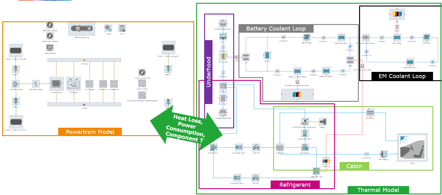
As the optimized interplay of the systems on board of the vehicle systems became crucial for vehicle efficiency, so did the need to consider all of them in the same simulation model. AVL CRUISE™ M is capable of modelling all the relevant system. These include electrical networks, mechanical and thermal systems as well as a generic data and function network for control tasks. This allows you to correctly predict the efficiency and heat loss on a component level, optimise the individual subsystems and the overall system in detail.
The set-up of a detailed vehicle thermal management system model is of course no small feat. To assist engineers and reduce the modelling effort, CRUISE M offers a wide array of parameterization wizards and generators available in its Efficiency Portal.
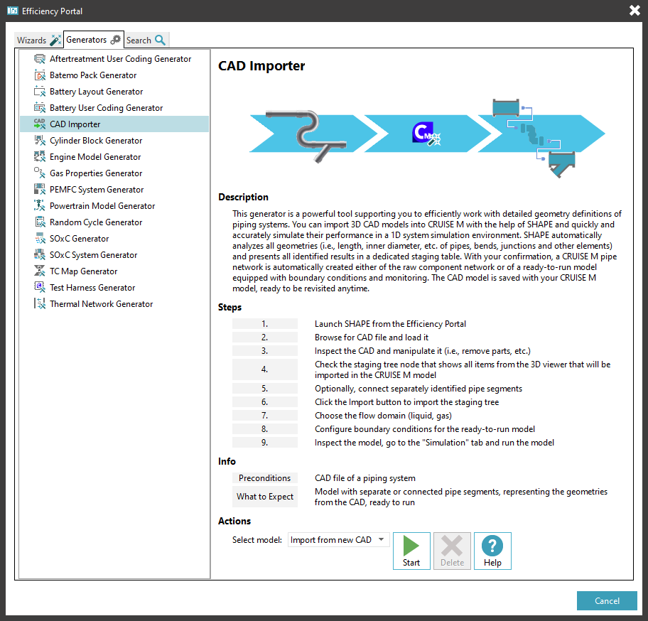
Commonly, only the pressure drop characteristics of key components, such as the heat exchangers and valves are considered in the concept phase. But complex cooling systems also comprise numerous pipes and hoses of various shapes that impact the system curve and as such influence the performance of the system. Once the development process is in a late enough stage, the model created in the concept phase must be updated with bends, restrictions, orifices, tubes and hoses to reflect the real system behaviour. Due to the complexity of such piping systems and the elementary modelling nature this would be a very tedious task for the simulation engineer. Automatic generation of piping systems based on an imported CAD file is therefore extremely beneficial.
Starting the CAD Importer will open SHAPE, a tool to import, clean and manipulate CAD data. Upon import (most common formats are supported), the geometry is automatically analysed and topological elements required for the generation of the CRUISE M model are identified. This comprises the identification of pipes, bends, junctions and their geometrical properties. All of the identified components are then placed in a dedicated staging list, allowing the user to inspect the data, hide/select parts of the model and create larger assemblies, by e.g. connecting multiple pipes to one pipe group before generating a corresponding CRUISE M model.
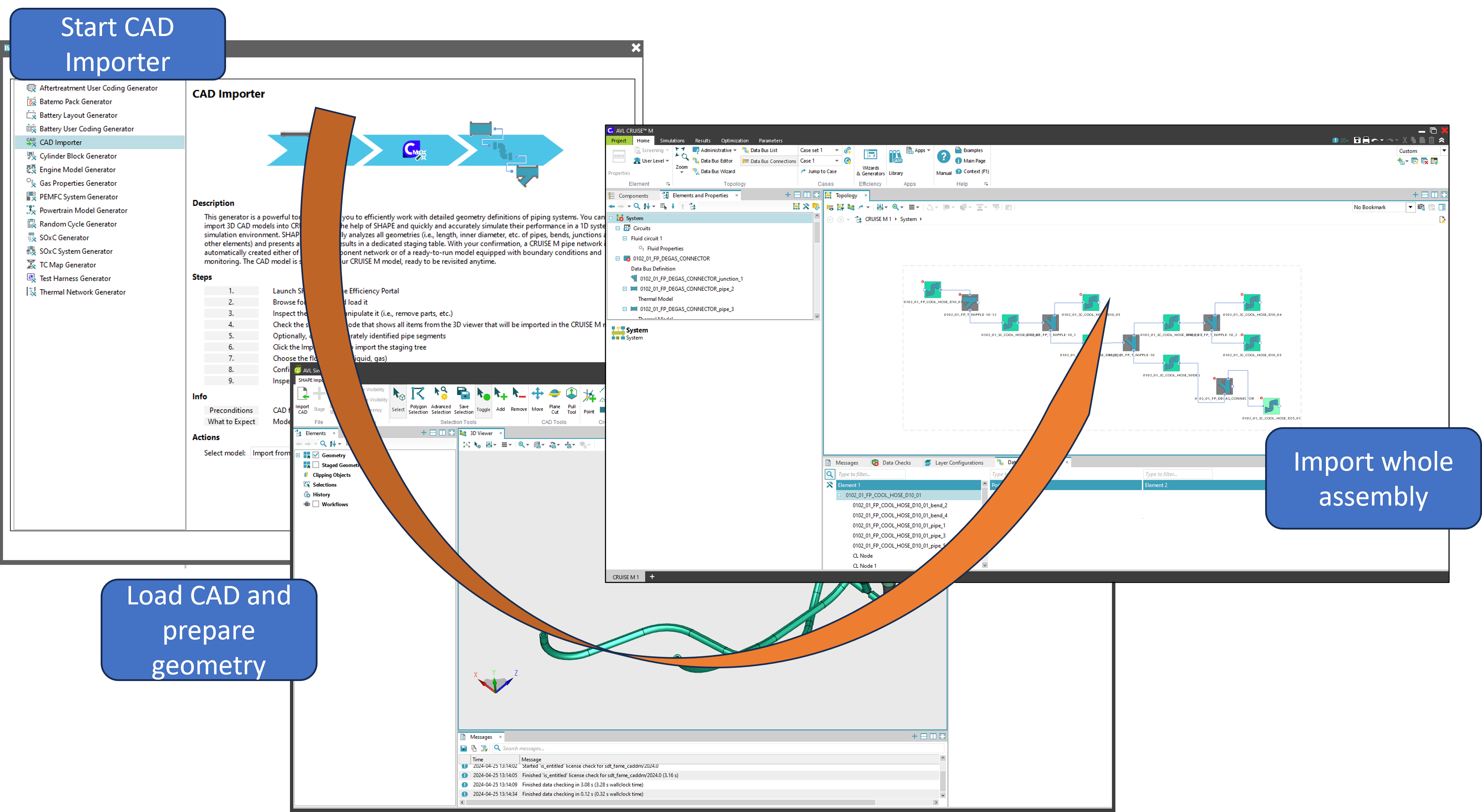
The calibration of refrigerant components, such as chillers, evaporators and condensers presents a significant challenge due to the complex physical phenomena occurring in these components. Since the refrigerant undergoes a phase change, the heat transfer and pressure drop will heavily vary depending on the state of the refrigerant. Because of that, complex and numerically demanding calculations are required to correctly describe pressure drop and heat transfer. Compared to single phase flow, even defining the boundary conditions is more challenging as an additional variable (refrigerant pressure) needs to be considered.
To reduce the required level of expertise and expedite the calibration process, CRUISE M offers a calibration wizard for two types of refrigerant heat exchangers:
- MPET (multiport extruded tube) heat exchangers (commonly used for evaporators and conventional, air-cooled, condensers)
- Plate heat exchangers (commonly used for chillers and liquid cooled condensers)
The user must provide the heat exchanger geometry and a heat transfer and pressure drop dataset (multiple formats are supported). It is also possible to choose between multiple heat transfer and pressure drop correlations to improve the fitting. After the completion of the calibration process, all the calibrated parameters are automatically transferred to the heat exchanger component and can be used as part of the refrigerant circuit.
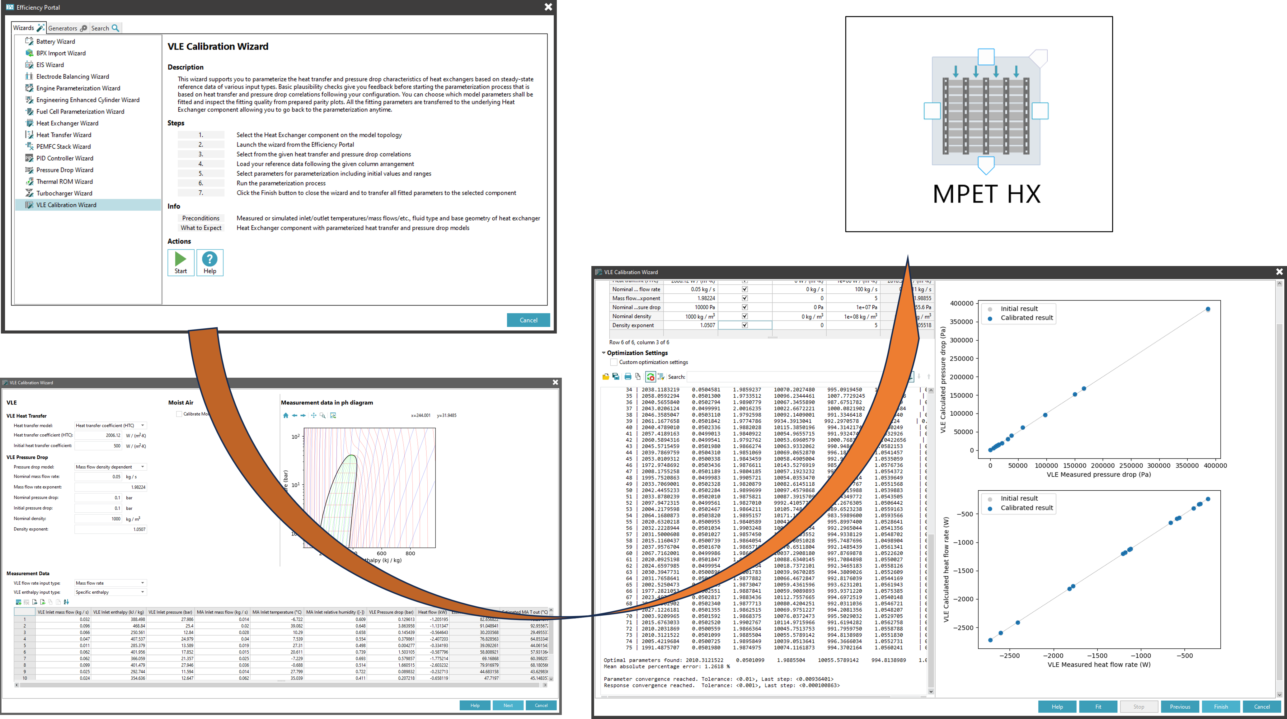
One of the challenges in the early stages of the vehicle thermal management system development process is not having enough data to sufficiently parameterize the model. This is typically a consequence of not yet having selected the components that will be installed into the production vehicle, e.g. the main radiator. But it is almost always possible to estimate the space available for the radiator and estimate the performance of such a radiator based by means of applying standard heat transfer and pressure drop correlations. Based on the predicted heat losses of the, such a tool can also be used to determine the microgeometry (e.g. fins and louvres) required to meet the heat transfer requirements in the limited packaging space.
Engineers can use the heat exchanger wizard that guides them through a series of input pages.
- In the first one, the overall size of the heat exchanger is defined, followed by the configuration of geometrical details on the tubes, fins and louvers.
- Up next, the pressure drop and heat transfer correlations for both media can be defined. The user can choose between using CRUISE M’s default correlations or custom Nusselt correlation. The flow arrangement (concurrent flow, counter flow, cross flow, etc.) must be selected in this page as well.
- In the third page, the liquid types and the operating ranges (temperature and flow rate) of both streams must be defined.
- The next two pages give an overview of the calculated heat exchanger performance, including heat transfer, outlet temperatures, Reynolds numbers, effectiveness and more.
Upon completion of the wizard, the heat exchanger is parameterized and placed into the model topology where the simulation engineer can use it in a larger model.
Stay tuned
Don't miss the Simulation blog series. Sign up today and stay informed!
Read More About This Topic
Data gives one the confidence to clearly decide which concepts to follow. A solid data basis is especially important when mobility concepts are evaluated with regard to multiple factors at the same time. This is exactly what AVL CRUISE™ M stands for.

The fourth part of this online event series focuses on AVL's simulation solution for electric drive development. Learn about the opportunities that virtualizing can provide. Especially when it comes to using a consistent set of simulation tools for a streamlined workflow.

In many markets, battery electric vehicles have yet to achieve the same level of acceptance as combustion engine vehicles. To make them more competitive, it is essential to reduce the cost of EVs and build confidence in their safety.
Stay tuned for the Simulation Blog
Subscribe and don‘t miss new posts.