
Simulation of Anion Exchange Membrane (AEM) Electrolyzers With AVL FIRE™ M
Published on January 08, 2025 · 10 min read
Todays relevant types of water electrolyzers are:
- Alkaline electrolyzer
- Proton exchange membrane (PEM) electrolyzer
- Solid oxide electrolyzer
Alkaline electrolyzers are cheap due to the possibility to use non-noble catalyst materials, but suffer from low power density and low efficiency. PEM electrolyzers, on the other hand, have a high power density and efficiency, but are expensive, since noble catalyst materials (e.g. iridium) are needed. Solid oxide electrolyzers offer the highest efficiency, but have durability issues and are expensive as well.
AEM electrolyzers are basically a mixture of alkaline and PEM electrolyzers. In AEM electrolyzers the diaphragm located between the electrodes, as it is applied in alkaline electrolyzers, is replaced with an ion exchange membrane. AEM electrolyzers are supposed to combine the best of two worlds: The low cost of alkaline electrolyzers is combined with the high efficiency of PEM electrolyzers.
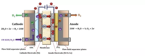
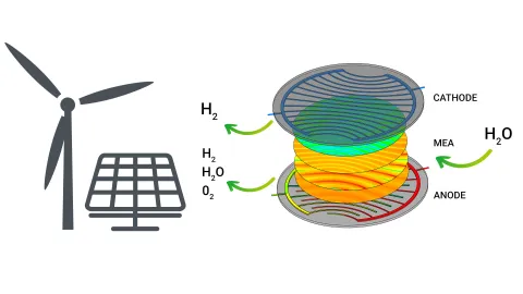
Figure 1 shows a schematic view of the AEM electrolyzer working principle. AEM electrolyzers are a mixture of alkaline and PEM electrolyzers. In the electrodes the same reactions as in alkaline electrolyzers take place. As in PEM electrolyzers, the electrodes are separated by an ion exchange membrane. Whereas PEMs conduct hydrogen protons, AEMs conduct hydroxide anions. The membrane material is a complex polymer electrolyte containing positively charged cationic groups bound covalently to a polymer backbone. As in PEMs, the AEM’s ability to conduct ions is proportional to humidity. Since the mobility of hydroxide ions is smaller than that of hydrogen protons, the dependency on humidity is more important. Theoretically, AEM electrolyzers can be operated with pure (distilled) water. However, to increase the performance, usually weak electrolyte solutions (e.g. water with 5% KOH) are used. The higher hydroxide concentrations in the system lead to an increase of membrane conductivity and catalyst utilization.
AEM electrolyzers are still in early research and development stage (e.g. the Wikipedia page has been created at the beginning of 2023). One of the major challenges is the durability of the membrane which is the main reason for the lifetime limitations of AEM electrolyzers. Currently, the AEM electrolyzer lifetime is approximately one tenth of the PEM electrolyzer lifetime. Therefore, research efforts focus mainly on the development of the membrane material, not only in view of durability, but also in view of high ionic conductivity and small gas permeability.
Since the technology is very new, there are only very few publications about modeling of AEM electrolyzers. The model implemented in FIRE M is based on the PEM electrolyzer model already existing in FIRE M extended by the model by Stanislaw et al. [2]. In addition to the equations solved for the PEM electrolyzer (gas/liquid two-phase flow, gas species transport, electronic charge transport, ionic charge transport in the membrane, dissolved water and gas species transport in the membrane, heat transport) additional transport equations are solved for the ion transport in the liquid electrolyte and the ionomer phase of the membrane. Here, proper relations are derived from the Nernst-Planck equations for binary electrolyte solutions and ion exchange membranes. The related new solution quantities are the ion concentrations in the liquid electrolyte and the ionomer as well as the ionic potential in the liquid electrolyte. In the catalyst layer, the hydroxide ions from the electrolyte solution are transferred into the ionomer phase of the membrane. For this ion mass transfer a proper mass transfer model is added.
From the numerical point of view, the AEM electrolyzer model is even more challenging than the PEM electrolyzer model, since more quantities (ionic potential and ion concentration) are defined in the liquid phase. As already pointed out in the past, the proper convergence of the liquid water, especially in the porous media, is a challenging task. With this stronger dependency on the liquid phase, the slightest oscillations in the solution of the liquid water are amplified and affect the overall convergence in a stronger way. However, all those numerical challenges have been mastered and a converged solution can be achieved in an acceptable calculation time.
One of the major goals in the design and optimization of AEM electrolyzers (and all electrolyzers and fuel cells in general) is a homogeneous ionic current density distribution in the membrane (or electrode separator). If the current density looks as shown in Figure 2, one should carefully analyze the causes for those inhomogeneities.
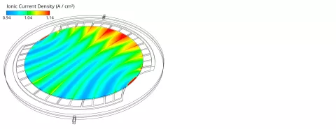
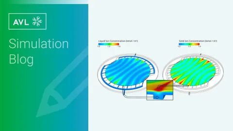
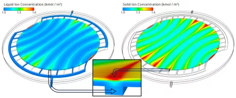
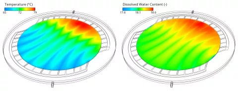
Three main influencing quantities for the current density distribution have been identified: the hydroxide ion concentration, the humidity (dissolved water content) and the temperature. As shown in Figure 3, the hydroxide ion concentration decreases from the anode catalyst layer towards the cathode channels due to the consumption in the electrochemical reaction at the cathode. The convective transport of hydroxide ions across the GDL to the neighboring channels causes local concentration peaks above the channels. Since the current density depends proportionally on the ion concentration, those peaks cause the local current density to peak as well, as shown in Figure 2.
The global increase in the current density from left to right can be attributed to the strong temperature gradient which is shown in Figure 4 on the left side. The higher temperature increases the electrochemical reaction rate, the ionic conductivity and the water diffusion coefficient which facilitates the water transport from anode to cathode. The latter leads to an increase in the dissolved water content (see Figure 4 right) which increases the ionic conductivity as well. Obviously, high temperatures are beneficial for the performance, but, on the other hand, accelerate the aging. Therefore, such as current density peaks, also temperature peaks should be avoided to ensure a long lifetime of the cell.
As all electrochemical energy devices, also AEM electrolyzers suffer from aging caused by degradation of single components and materials (specifically the membrane) reducing the lifetime. To predict the cell performance under aged conditions and estimate the lifetime, proper degradation models are required. For PEM fuel cells such degradation models are already available in FIRE M. In future, degradation models shall be available for electrolyzers as well.
The type of water electrolyzer with the highest degree of maturity and the only electrolyzer technology currently installed on an industrial scale is the classical alkaline electrolyzer. A simulation model for this type of electrolyzer is available since Release 2024 R2.
Anion exchange membrane (AEM) electrolyzers are a promising candidate for future green hydrogen production, since they are cheap and efficient. Although AEM electrolyzers are still in the early research and development stage, FIRE M already contains a dedicated simulation model for AEM electrolyzers. The model for PEM electrolyzers has been extended by the proper electrochemical reactions, additional transport effects in the liquid electrolyte as well as ion mass transfer between liquid and ionomer phase in the catalyst layers. As shown in the 3D results section, the ionic current density in the membrane depends, in addition to humidity and temperature, on the ion concentration. Higher ion concentrations in the feeding electrolyte solution enhance the performance.
[1] https://www.linkedin.com/pulse/aem-water-electrolysis-zhongpeng-guo-dxj…
[2] L. N. Stanislaw, M. R. Gerhardt, A. Z. Weber, ECS Transactions 92(8), 2019.
Stay tuned
Don't miss the Simulation blog series. Sign up today and stay informed!
Learn More About This Topic
Aiming at a drastic CO₂ reduction in industry and mobility, the world is currently facing the challenge of producing green hydrogen at affordable prices and in sufficient quantities.

With the demand for non-fossil energy, solid oxide fuel cell systems and electrolyzers have taken their place in stationary power generation. Their advantage is obvious: They are local, well-scalable and highly efficient systems.
The demand for sustainably generated energy is increasing rapidly, and electrolyzers are seen as a promising technology. Due to their efficiency and good dynamic performance, PEM electrolyzers are one of the most widely used technologies today.
Stay tuned for the Simulation Blog
Subscribe and don‘t miss new posts.