
Virtual Design and Optimization of Alkaline Electrolyzers With AVL FIRE™ M
Published on March 25, 2025 · 10 min read
Beside the high degree of maturity, alkaline electrolyzers offer a number of additional advantages, e.g.:
- Cost-effectiveness in production and operation: e.g. due to non-noble catalyst materials
- High durability: robust, also for large plants
- Scalability: large plants possible
- Tolerance for impurities: less need for water purification
Especially compared to PEM electrolyzers, there are also some disadvantages:
- Lower efficiency
- Less dynamics
- Safety concerns: gas crossover leading to mixing of hydrogen and oxygen
- Larger footprint: big systems
- Low pressure operation
Modern designs of alkaline electrolyzers (e.g. zero-gap design) and intelligent operation strategies have the potential to partially overcome the efficiency limits. In that context, 3D CFD comes into play by offering attractive virtual optimization techniques.
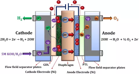
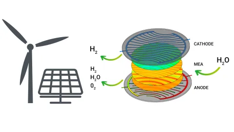
The cathode is fed with a highly concentrated liquid electrolyte (e.g. KOH dissolved in water). The electrolyte solution is then transported either through flow channels or through some type of distributor (e.g. expanded metal mesh) to the cathodic electrode where water reacts to hydrogen and hydroxide ions by consuming external electrical energy. The produced hydrogen leaves the system through the cathode outlet whereas the hydroxide ions are transported across a diaphragm to the anodic electrode where water, oxygen and electrons are produced. Theoretically, only one inlet for the liquid electrolyte is necessary. However, due to a better electrolyte circulation leading to a more stable operation and improved performance, the liquid electrolyte is often fed to cathode and anode.
The most critical component of the alkaline electrolyzer is the diaphragm which is used as a separator between the electrodes. Here, a porous material with the following requirements is needed:
- High gas separation efficiency
- Chemical stability in the highly alkaline environment
- Mechanical and thermal stability
- Low electrical resistance for the ion transport
- Long durability
Common materials used for diaphragms include asbestos (historically), polysulfone, and advanced composites like Zirfon, which combines zirconia and polysulfone for enhanced performance. The pore size and porosity are usually in the range of 100 nm and 50%, respectively.
As a catalyst material usually non-noble metals, such as Ni, are applied.
The alkaline electrolyzer model in FIRE M includes the following transport effects:
- Two-phase flow with capillary effects in porous media, phase change, momentum exchange gas/liquid and electro-osmosis
- Gas species transport with multi-component diffusion
- Three-phase enthalpy transport with the porous solid as the third phase
- Dissolved gas species transport in the liquid electrolyte
- Electronic charge transport in the solid phase
- Ionic charge and ionic mass transport in the liquid phase
The electrochemical reactions, taking place in the electrodes, are modeled with the Butler-Volmer equation, as usual. Compared to the PEM electrolyzer, there are additional terms for ion concentration and liquid water saturation in the pre-exponential term. The model is based on the following assumptions:
- The gas phase transport and phase change in the diaphragm is not included, i.e. gas species can cross the diaphragm only in the dissolved state.
- Electrodes must be porous, i.e. solid electrodes are not supported.
- H2 and O2 are produced in the dissolved state within the liquid electrolyte and form gas bubbles according to the local phase equilibrium.
- In contrast to previous models, e.g. for PEM electrolyzers, the alkaline electrolyzer model has a higher flexibility regarding the position of the electrodes. Beside the zero-gap design, i.e. electrodes touch the diaphragm, gaps between diaphragm and electrodes are allowed.
One of the major goals in the design and optimization of alkaline electrolyzers (and all electrolyzers and fuel cells in general) is a homogeneous ionic current density distribution. Figure 3 shows the geometry, the ionic current density distribution in the diaphragm as well as relevant contributing quantities, i.e. liquid water saturation, temperature and ion concentration. The current density decreases from the bottom (channel inlets) towards the top (channel outlets). The main reason for that is the decrease of the liquid water saturation from inlet to outlet, since the reaction rate is directly proportional to the water saturation. The liquid water distribution, in turn, is influenced by the current density: The water consumption at the cathode causes a depletion of liquid water.
An additional effect originates from the gravity which leads to a stronger balancing of the liquid water saturation by pulling the water downwards and pushing the gas bubbles upwards. Higher temperature and higher ion concentration are directly proportional to the current density as well, since they increase the reaction speed and in general also the diffusivities and conductivities. Both quantities have smaller values at the bottom and, therefore, weaken the current density gradient. The temperature is smaller at the bottom due to the cooling effect of the inlets and smaller at the anode due to the reversible heat (entropy) contribution in the electrochemical reaction. The ion concentration is higher at the top, since the ions produced in the cathode reaction are being pushed upwards by the stream of the liquid electrolyte.

Figure 4 shows the distribution of the gas components of interest, i.e. H2 and O2, in the main compartments, i.e. in the compartments where the gas components are produced. Since H2 bubbles are lighter than O2 bubbles, they experience a stronger influence of buoyancy leading to a larger volume fraction at the upper part of the cell.
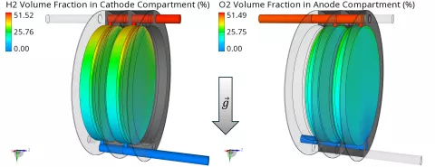
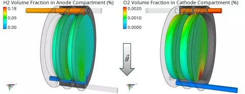
Finally, the H2 and O2 volume fractions in the opposite compartments are shown in Figure 5. Those unwanted gas accumulations are caused by gas crossover across the diaphragm and should be minimized to prevent a dangerous mixture of H2 and O2. Obviously, the accumulations of H2 are much higher compared to O2. The reasons are a faster diffusive transport (larger diffusion coefficient for H2) and additional convective transport due to the electro-osmotic drag which acts towards the direction of the anode.
In an alkaline electrolyzer, several components, such as electrodes, diaphragm or current collectors, are critical regarding aging and long-term performance, mainly due to the aggressive alkaline electrolyte solution. Additionally, contaminations of the liquid electrolyte can reduce the performance over a longer period. The operational lifetime requirements for alkaline electrolyzers are about 60,000 to 90,000 hours. Thus, the aging of components should be avoided as well as possible. To predict the performance losses as a function of the lifetime and identify the most critical locations and operating conditions, degradation models are required. Therefore, in the future, degradation models for alkaline electrolyzers will be added to the performance model of FIRE M.
Alkaline electrolyzers are supposed to be the leading technology in the production of green hydrogen over the next decades. Virtual design and optimization with the help of a 3D CFD tool are a crucial foundation in the development and improvement of that technology. In this article, the alkaline electrolyzer model included in the release 2024 R2 of FIRE M has been introduced. In the 3D results section, the influence of water saturation, temperature and ion concentration on the local performance has been shown. Additionally, the H2 and O2 distributions in the gas phase have been presented and the effect of gas crossover has been pointed out.
Stay tuned
Don't miss the Simulation blog series. Sign up today and stay informed!
Like this? Maybe you’ll also enjoy these…
Aiming at a drastic CO₂ reduction in industry and mobility, the world is currently facing the challenge of producing green hydrogen at affordable prices and in sufficient quantities.
The demand for sustainably generated energy is increasing rapidly, and electrolyzers are seen as a promising technology. Due to their efficiency and good dynamic performance, PEM electrolyzers are one of the most widely used technologies today.
Stay tuned for the Simulation Blog
Subscribe and don‘t miss new posts.