Different global requirements demand flexible solutions. Since you know your needs best, you are the ideal developer of your fuel cell and electrolysis system.
Once the system requirements are defined, it is a matter of balancing all the individual parts of the system. At the stack and module level: You need to look at fuel/air species supply and distribution, thermal load, and conversion efficiency under quasi-steady and transient operating conditions such as start-stop or SOFC/SOEC mode switching. Furthermore, in addition to optimized performance of the Balance-of-Plant (BoP) components, test their durability under all relevant load and operating conditions.
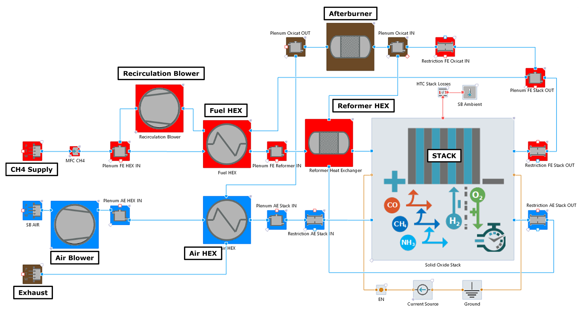
At the system level, the BoP components – selection and sizing of compressor and blower, injector and ejector, evaporator, reformer, start-up burner, HC afterburner, etc., the design of the air and fuel supply system, the configuration of the thermal management system and, of course, the calibration of the control strategy – can then be tuned.
Global Requirements
As on-site units, stationary systems must meet the respective requirements of their target markets. The systems must therefore be designed to be as flexible as possible.
Power Density
Requires accurate system design, optimized BoP components, and uniform air and fuel supply to all cells in the stack.
Efficiency
In addition to the conceptual design of the fuel cell or electrolysis system, the dimensioning of the BoP and the optimal supply of the stacks and modules is crucial.
Durability
A well cooled system, optimal media distribution and control strategy are critical.
Cost
Physical development work and testing require prototypes, test beds, time and manpower.
To minimize the risk of conflicts in terms of energy density, efficiency and durability, you can develop a system holistically right from the start. Simulation is particularly suitable for taking these targets into account from the very first concept, well before there is even a prototype. In addition, adaptions to different requirements can be easily performed and tested virtually.
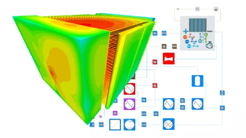
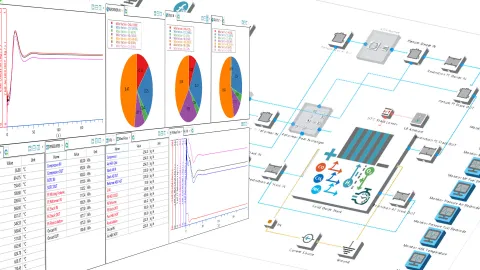
Our one-platform solution enables the ideal interaction of 3D multi-physics CFD and system simulation. (Find out more) You can use the software from the first development steps throughout the entire V-process. Optimize efficiency and performance with power and degradation models for SOFC and SOEL stacks. With the System Simulation option, developing and calibrating FCCU functions in SiL and HiL environments is no problem thanks to full real-time capability.
Scalable SImulation Solution
Supports you throughout the entire development process of solid oxide fuel cells and electrolyzers.
Consistent SOFC/SOEC Stack Performance and Degradation Models
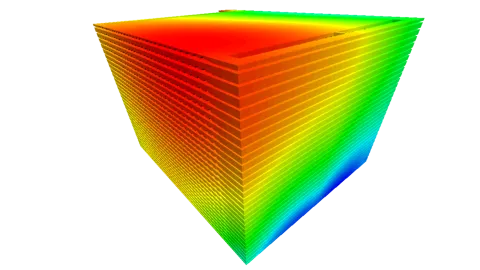
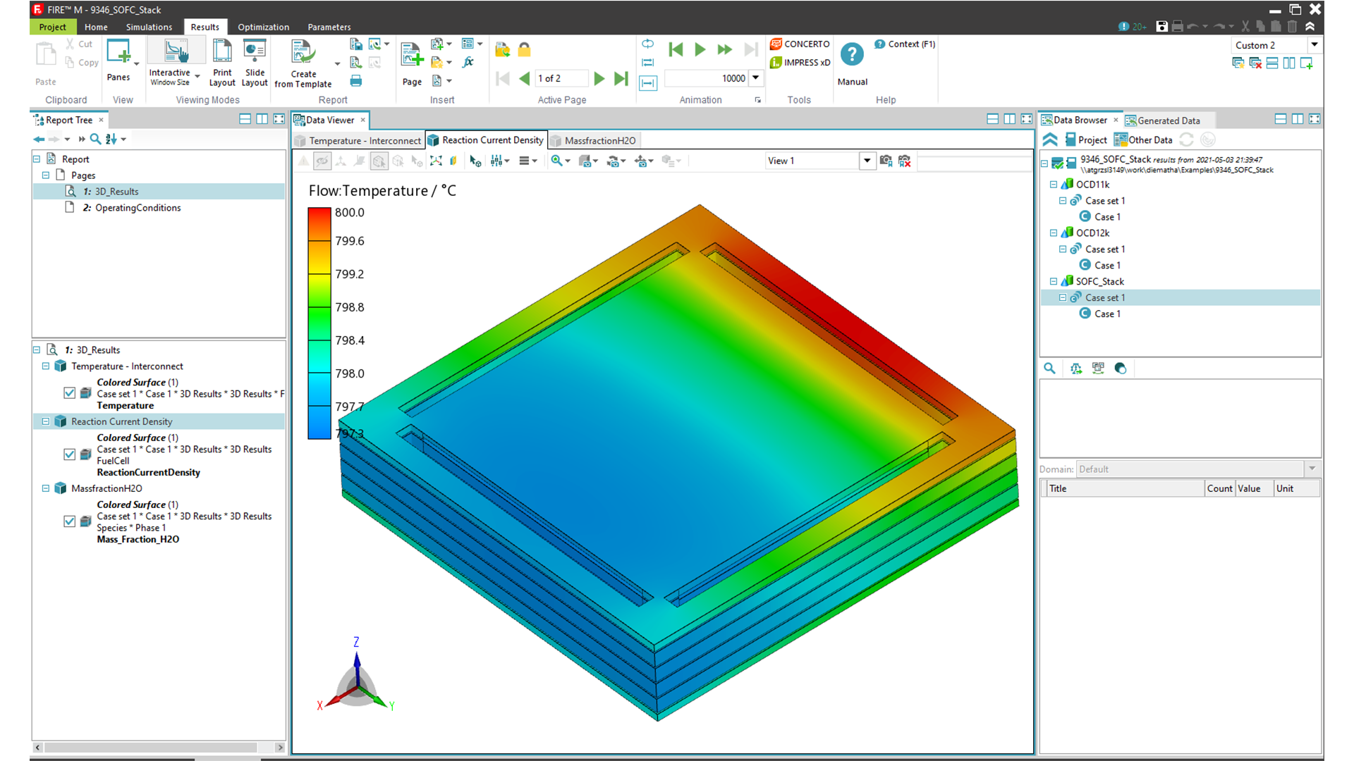
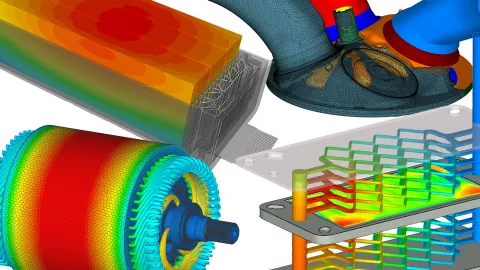
3D multi-physics CFD and system simulations provide accurate information on the major degradation processes in the stack and enables evaluation of their impact on global aging characteristics under dynamic operating conditions.
One-Platform Solution
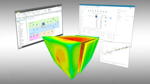
Facilitates the sharing of data between tools and teams. Additionally supported by the common graphical user interface (GUI).
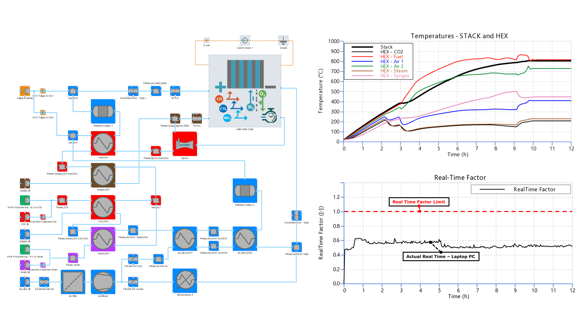
Real-Time Capable Stack Models With Reduced Dimensionality (RD) For SOFC/SOEC
Increases your efficiency in the development and calibration of system control and in the testing of components and subsystems in SiL and HiL environments.
Model Parameterization Wizard
Our system simulation software AVL CRUISE™ M features parameterization wizards for solid oxide fuel cells and electrolyzers. The guided workflow facilitates and accelerates the parameterization of the cells.
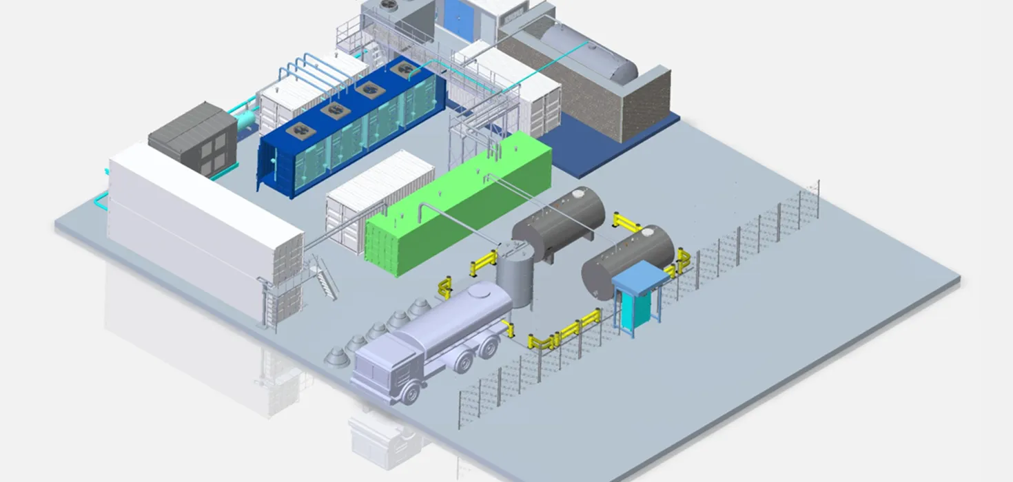
Scalable BoP Component Modeling
To ensure the highest possible performance at maximum efficiency, our 3D CFD tool AVL FIRE™ M and CRUISE M 1D/0D system simulation provides flexible modeling of
- Compressor,
- Injector and Ejector,
- H2 tank,
- Evaporator,
- Reformer,
- and much more.
Guided 3D Multi-Physics CFD Workflows
- Embedded Body Method: Reduces mesh creation time from days to minutes.
- Homogenized channel approach: Enables rapid studies of geometry variations at cell, stack, and module level.
AVL White Paper – Electrolyzer Simulation Performance and Lifetime
Discover how simulation enhances electrolyzer development by boosting efficiency, durability, and integration with renewable energy sources.
To develop a truly efficient and durable polymer electrolyte fuel cell (PEM) system , engineers must have insight into the basis of the system - the cell. The transport of hydrogen and oxygen, the electrochemical reaction processes, the membrane structure, the aging mechanisms, the supply of each cell in the fuel cell stack, and much more are ...
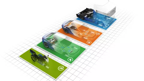
Data gives one the confidence to clearly decide which concepts to follow. A solid data basis is especially important when mobility concepts are evaluated with regard to multiple factors at the same time. This is exactly what AVL CRUISE™ M stands for.
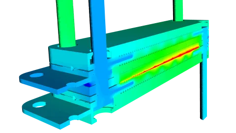
Due to its scope, AVL FIRE™ M can be described as all-purpose CFD software. However, it is mainly used for the development of all types of powertrains and their components.
The software allows you to view flows around vehicles and objects or heat transfers between any fluid and solid domains in detail.
Aiming at a drastic CO₂ reduction in industry and mobility, the world is currently facing the challenge of producing green hydrogen at affordable prices and in sufficient quantities.
Immerse yourself in the world of Solid Oxide Fuel Cell (SOFC) physical modeling in our exclusive webinar and learn how to use the impressive capabilities of AVL CRUISE™ M in combination with ESTECO's intelligent optimization tool modeFRONTIER.