The well-known hydrodynamic (HD) joint group from EXCITE Power Unit has now been migrated to EXCITE M. This group consists of the Advanced Axial Slider Bearing (AXHD), Advanced Radial Slider Bearing (EHD2), and the Advanced Sliding Guide (EPIL). This transition not only encompasses a new GUI for the HD joint group, but also simplifies and improves many model configurations with better visualization opportunities, data checking and integrated workflows within the AVL Simulation Desktop environment. This includes the usage of data pool elements and live scripting, to name a few.
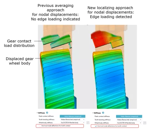
The Advanced Cylindrical Gear Joint (ACYG) has been capable of considering flexible gear wheel body deflections from circumferential nodes placed at the root of the teeth. However, the applied mapping method performs some averaging, resulting in specific gear wheel body deflection shapes (such as the well-known "potato-chip" mode) not being sufficiently reflected in the contact-load distribution between the individual teeth. A new mapping method has been introduced as an option, considering only body deflections that are affected by the gear contact. With this method, local body modes will influence the development of the gear contact pattern in a much more realistic way.
Existing models using "Wheel body stiffness" = "Via EXCITE M flexible body" will not be automatically migrated to the new mapping method. Should the new method be desired, it requires explicit activation.
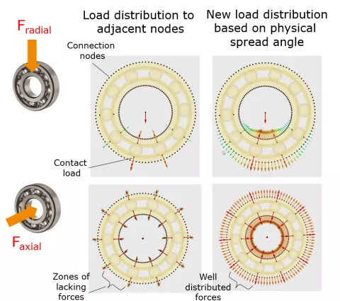
To ensure a more physical transmissibility of contact loads to circumferential connection nodes, a new approach has been implemented. It assumes a spread angle within which the single contact loads are applied to the connected structure. By that the load distribution effect due to the ring and seat rigidity is approximated and the load transfer becomes smoother and thus more realistic. As a result, unwanted artificial excitation effects are significantly reduced.
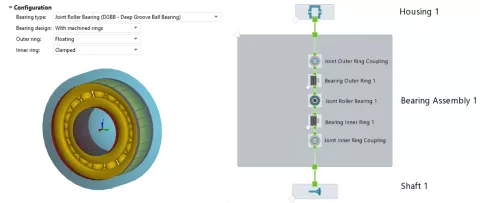
The modeling process of floating bearing systems and preloaded bearings is time-consuming and requires significant manual effort. Floating bearing configurations require the outer and inner ring to be modeled as separate bodies. You need to create, configure, and connect these bodies and the required joints. Moreover, you need to set the mass and inertia of the rings.
The predefined assembly automatically creates the ring bodies, inserts, and connects the required joints, estimates the mass and inertia of the rings, applies the preload on the related bodies, and automatically positions the rings. This assembly reduces the modeling time and ensures a proper modeling of the ring bodies.
The target speed and torque limit input of the Speed Controller can now be defined via 1D tables directly in the component dialog. Additionally, it is now possible to define separate lower and upper torque limits.
For quasi-stationary simulations, where the target speed for the controller is constant, a new "Initiation Interval" gain type has been added. With this option the controller gains are reduced to zero after a defined initiation phase. This way, only the main speed of the system is controlled, but other oscillations in the system are preserved.
For the Angle Discrete Speed Controller, the controller gains can now be defined based on speed using the new "Speed Dependent" gain type. This is necessary for run-up simulations with large differences in the speed of the system in order to guarantee a good controller performance for the whole speed range. For a simpler usage, default values are provided. However, you also have the option to manually input values to further tune the controller, if necessary.
EXCITE M provides a dedicated current controller for each e-motor type. It realizes the standard control strategy for transient drive. Moreover, the modulator offers the common strategy for field-oriented control.
Actual current controllers might not fit into this framework, but their differences might be relevant to dynamic interaction with the electric system. For this reason, an open current controller is offered as an alternative to the built-in variants. Relevant input and output signals are exchanged to three different platforms: MATLAB Simulink, Model.CONNECT™ and Compiled Function that allows C-based function coding.
To simplify the connection between the e-motor and inverter in EXCITE M and the control, an example is shipped that contains a Simulink representation of the built-in controller for a permanent magnet synchronous motor.
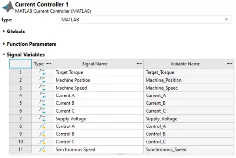
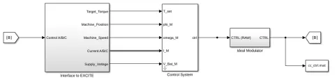
Figure 6: Generic Blocks in the Simulink® Template for the Current Controller
A time delay of one step is applied in EXCITE M to avoid an algebraic loop. Furthermore, with the open controller, switching events are handled only with the subsequent time step, whereas the built-in modulator triggers time events to switch at the actual time.
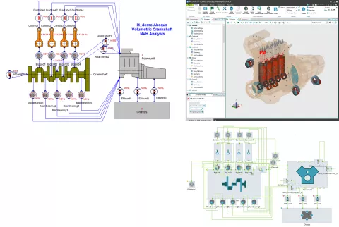
We have added the ability to export models from EXCITE Power Unit to EXCITE M. You can export entire models or just selected elements, as well as parts merged to existing models.
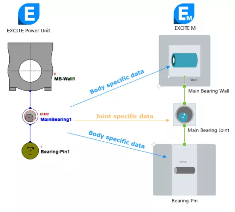
Models converted to EXCITE M will not look the same as in EXCITE Power Unit, and input parameters may be moved to different locations. EXCITE M strictly separates the data related to bodies and joints, keeping the geometry information on the bodies. Load applications and predefined motions for bodies are also specified in a different way than in EXCITE Power Unit. The export feature converts as much data as possible into the new EXCITE M model, but due to the differences in modeling, it is recommended to carefully inspect the exported model and in many cases it will pay off to manually adjust the models after export to make the best use of the new capabilities of EXCITE M.
There are some limitations in the first release of the export feature. The following joint types and model parts are not yet supported:
- EMC joint
- External model connections (Matlab)
- Valve Train subsystems
- Joints that are not yet available in EXCITE M like BELT, SLS, UNIV, etc.