
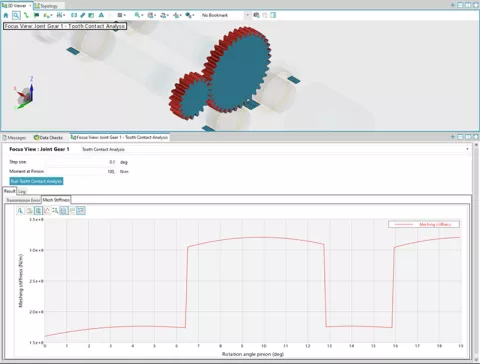
For application scenarios such as standard gearbox-NVH, optimization/DoE tasks and others EXCITE M offers you a faster solution: the new frequency domain solution (FDS). You can use FDS as an alternative to the well-known time domain solution (TDS) or as a supplement. The relevant sources for periodic excitation of e-axles are gear excitation forces. Analytical tooth contact analysis (TCA) is used to calculate these gear excitation forces.
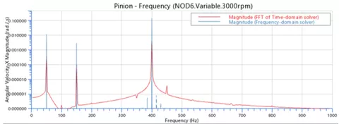
The solution provides results for all nodal body motion quantities (i.e., displacements / velocities / accelerations) over the analyzed frequencies.
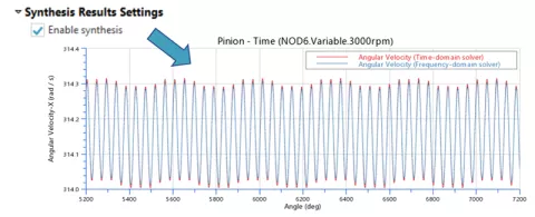
To display the results in other coordinate systems, the synthesis of the results in the angle/time domain is supported.
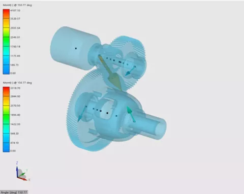
In addition to chart-based representations, you now have the option to animate the 3D FDS results in two different ways:
- By body motion at single frequencies (including data recovery of nodal quantities)
- By synthesizing body results that represent the combination of the single frequencies to a time and angle equivalent signal
Several new elements to model simple control system functionality are provided to be able to influence and control system behavior such as cylinder pressure application (e.g. via changing the throttle position) or performing switching actions in a drive system (e.g. actuating a clutch).
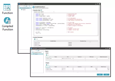
In addition, the possibility of integrating C-code in the form of so-called compiled functions allows basic control functions (e.g. a PI controller) to be incorporated. Co-simulation with external tools is no longer necessary.
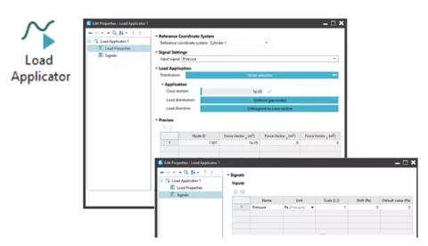
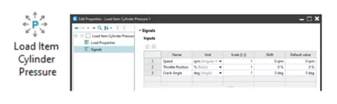
Another innovation concerns signals and control. A first set of components is now offered to you in the graphical front-end of EXCITE M): Load Applicator and Load Item Cylinder Pressure: Facilitate load application at body nodes (like pressure, force and moment) based on the specified input-signals.
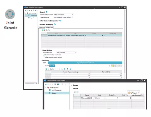
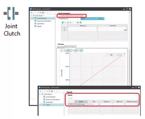
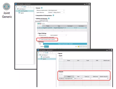
In order to model and actuate switching elements such as friction clutches, simple synchronizer units or dog clutches, the existing joint functionality has been extended. The extension includes the joint properties clamping force, stiffness/damping. These can now be set and scaled via input signals.
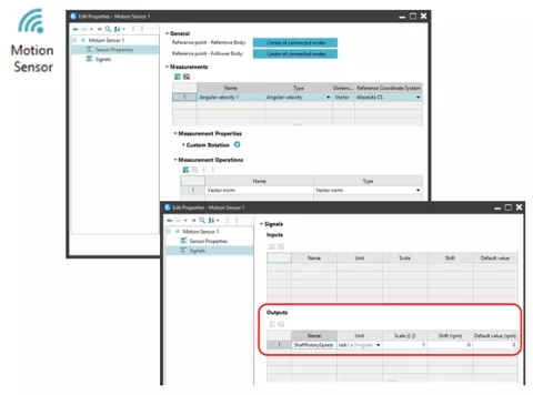
Measuring the rotary speed of a shaft/crankshaft at a specific node position relative to a housing or engine block is complex. This new component allows you to sense and process relative translational and rotational motions between the nodes of two bodies. Moreover, it provides you with basic functions for the conversion of 3D vector readings into single signals such as vector norm or scalar projection.
The existing Table Force/Moment Joint (FTAB) has been extended to perform basic force/moment measurement tasks. For each of the different FTAB options, the resulting force/moment can be accessed via an output signal provided by the joint.
The user can take any input and output signal of EXCITE model and use them in code that will perform a certain function in that model. Compilation of the C-code and link to EXCITE solver happens automatically and does not require any user action. This enables the user to significantly extend the functionality of EXCITE to fulfill his or her specific requirements.
It is now possible to connect EXCITE M with Model.CONNECT. This can be achieved using the new components. Any number of Model.CONNECT interfacing components can be arbitrarily added in the EXCITE M model. The Model.CONNECT components are part of the signal network in EXCITE M. This means that you have the possibility to define input and output signals for all EXCITE M quantities to be exchanged.

So far, EXCITE has offered joint types for acoustic analysis up to high frequencies of 20 kHz for all machine types. Now additional joint types and current controllers have been introduced to enable analysis of low-frequency problems in traction motor and hybrid applications.
EXCITE M offers following approach for electric motor joint:
- Map based (imported pre-calculated forces and moments) – available for all e-motor types with radial flux
- Parameter based (linear fundamental wave model) – available for PMSM (permanent-magnet synchronous motors), EESM (externally excited synchronous motors), SCIM (squirrel-cage induction motors) and SYRM (synchronous reluctance motors)
- File based – available for PMSM
o Saturated fundamental wave model – files for current dependent inductances and Permanent Magnet flux linkage
o MFC (Magnetic Field Computation) – files for phase-to-phase flux linkages and torque / stator tooth force / tooth axial moment
- ‘Axial-Axial’: Rotor axis nodes coupled to stator axis nodes (with or without consideration of rotor eccentricity)
- ‘Axial-Circumferential’: Rotor axis nodes coupled to stator teeth nodes (with or without consideration of rotor eccentricity)
New control systems have been introduced for the EESM and SCIM that reflect state-of-the-art current control for traction applications in motor or recuperation mode.