
EXCITE M supports the modelling of common configurations of internal combustion engines by providing an IC-Engine Assembly element.
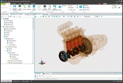
The element allows you to specify:
- IC-engine configuration (such as number of cylinders, their arrangement, several basic dimensions, and firing order)
- Model fidelity (such as usage of axial bearings, connection representation to be used for piston/liner guides and enabled degrees of freedom for certain components)
- Global geometry (such as bore and bearing dimensions) and cylinder pressure load
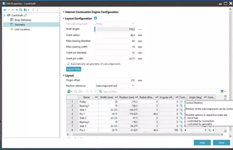
Based on the above inputs, the basic IC-engine model is automatically built. All parts of the model (bodies and joints, partly structured in sub-assemblies) are configured. Once the automatic setup of the base model is complete, the user can adjust certain parts or components to fit them to specific modeling and/or geometrical requirements. This could be related to the exact positioning of a pulley or flywheel on a crankshaft, for instance, or concern details regarding the node distribution used to connect the parts of the system.
In addition, the IC-Engine Assembly generates all sub-parts (link location types and positions) to enable the easy search of connection nodes or node sets. The condensation of FE models for flexible bodies is supported by the Component Modeler and enables the easy application of all used joints to the corresponding nodes on the connected bodies.
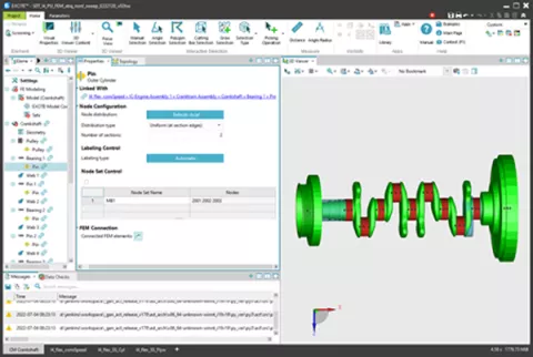
Working with existing condensed body representations is also possible. In this case, you can explicitly correlate the nodes and node sets in the FE model to the joint created in the IC-Engine Assembly. This step is supported by the select and search capabilities in the GUI.
A special cylinder pressure load definition has been introduced together with the IC-Engine Assembly to support the modeling of systems for transient dynamic analysis.
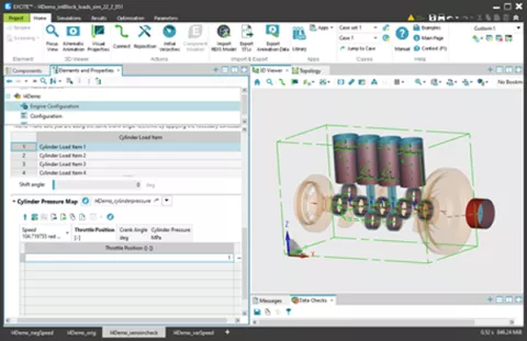
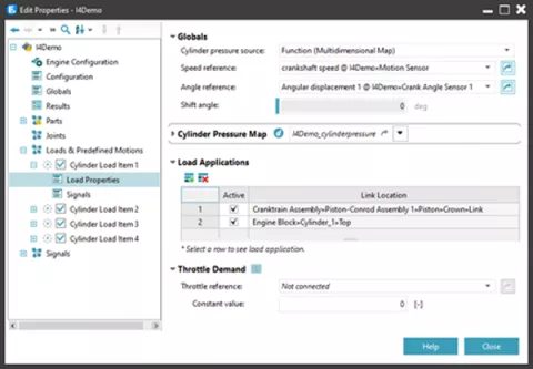
Cylinder pressure can be specified in a map as crank-angle-related pressure dependent on engine speed and throttle signal. The cylinder pressure is specified for a discrete number of operating points (engine speed or throttle position combinations). The reference quantities for the cylinder pressure load evaluation are defined with the load properties. Sensor elements can be used to determine the actual state of these quantities during the simulation.
- Speed reference can be set to a user-defined constant value or by using a sensor element to pick up an angular velocity of a body or a relative velocity between two bodies.
- Crank angle reference can use the same reference motion for all cylinders, or you can select reference motions from different sensors for the individual cylinders.
- Throttle demand can currently be defined by a user-defined constant value or by a table vs. time or reference angle.
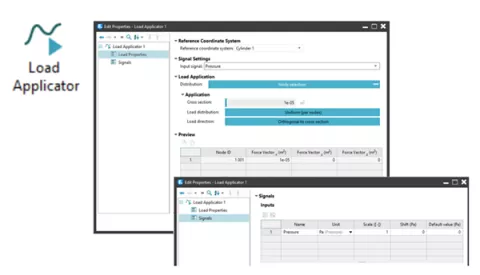
The correct transfer from specified cylinder pressure to appropriate load forces on the model components is defined in the Load Application panel. Two ways of load assignment are supported:
- Application of loads to nodes: Here, the type of the load signal can be defined (pressure, force, moment) and the distribution of the defined load to the individually connected nodes must be specified. For standard modeling cases, all required settings are done automatically based on the given IC-Engine Assembly data.
- Alternatively, the loads can be distributed to the body's connected nodes using load case vectors, prepared with the FE model of the body.
Several new elements to model simple control system functionality are provided to be able to influence and control system behavior such as cylinder pressure application (e.g. via changing the throttle position) or performing switching actions in a drive system (e.g. actuating a clutch).
In addition, the possibility of integrating C-code in the form of so-called compiled functions allows basic control functions (e.g. a PI controller) to be incorporated. Co-simulation with external tools is no longer necessary.
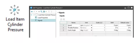
- Another innovation concerns signals and control. A first set of components is now offered to you in the graphical front-end of EXCITE M): Load Applicator and Load Item Cylinder Pressure: Facilitate load application at body nodes (like pressure, force and moment) based on the specified input-signals.
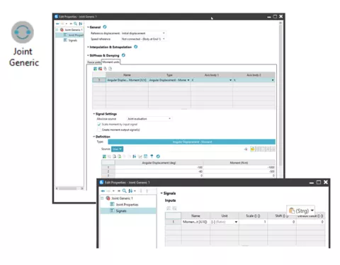
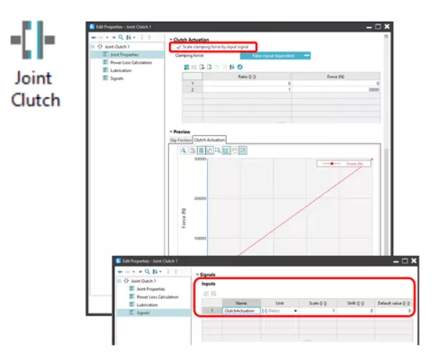
Elasto-Plastic Clutch Joint (EPCL) and Table Force/Moment Joint (FTAB): In order to model and actuate switching elements such as friction clutches, simple synchronizer units or dog clutches, the existing joint functionality has been extended. The extension includes the joint properties clamping force, stiffness/damping. These can now be set and scaled via input signals.
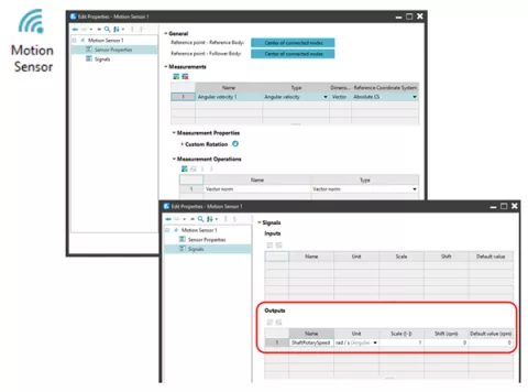
- Motion Sensor: Measuring the rotary speed of a shaft/crankshaft at a specific node position relative to a housing or engine block is complex. This new component allows you to sense and process relative translational and rotational motions between the nodes of two bodies. Moreover, it provides you with basic functions for the conversion of 3D vector readings into single signals such as vector norm or scalar projection.